IB-S201EF Dry-type transformer thermostat
Date: July 7, 2025 09:40:04
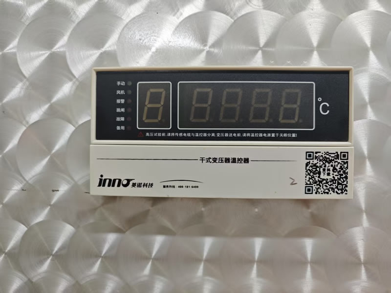
IB-S201EF is aDry-type transformer thermostatLtd., with a variety of functions, suitable for transformer temperature monitoring and control in the power system.
Functional Features
-
General FeaturesThree-phase circuit display/maximum value display, fan automatic/manual start/stop, over-temperature alarm, over-temperature trip, fault alarm, "black box" function, fan timing incentive function, analog test function, digital compensation function, cabinet door open alarm function.
-
4~20mA current output function (E): Provides three or four independent 4-20mA analog current outputs that can be used for integration with SCADA systems.
-
Communication function (F)RS485/232 serial communication function for remote monitoring and data acquisition.
Technical Parameter
-
environmental temperature: -20℃~+55℃.
-
Environmental humidity: <95% (25°C).
-
operating voltage: AC 220V (+10%, -15%).
-
operating frequency: 50Hz or 60Hz (±2Hz).
-
Measurement range: -30.0°C to 240.0°C.
-
Measurement accuracy: ±1%FS (thermostat class 0.5, sensor class B).
-
resolution (of a photo): 0.1°C.
-
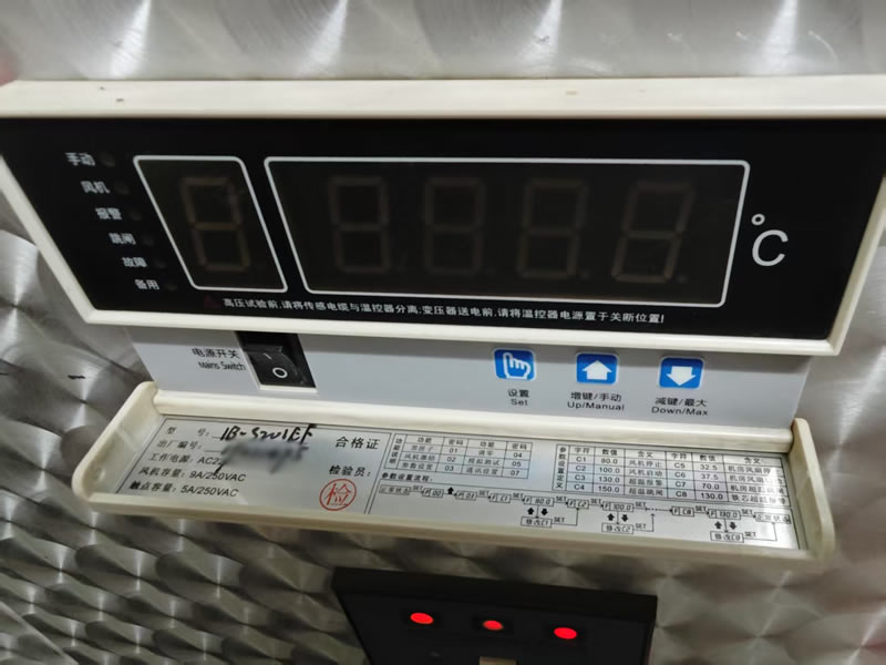
Fan Output Capacity: 9A/250VAC.
-
Control output capacity: 5A/250VAC; 5A/30VDC (resistive).
-
power wastage: ≤8W.
Mounting Dimensions
-
Hole Size: 152⁺¹mm × 76⁺¹mm.
-
Exterior Dimensions: 160mm × 80mm × 120mm.
Installation and use
-
Installation: For recessed installation, it is necessary to open a recessed hole in the transformer box according to the meter opening size.
-
connect a wire: Wire the thermostat according to the wiring diagram on the thermostat to make sure the connections are correct.
IB-S201EF thermostats are widely used in dry-type transformers in power systems to effectively monitor and control the temperature of the transformer to ensure the safe operation of the equipment.
Installation steps and precautions
-
Inspection equipment::
-
Prior to installation, inspect the thermostat and sensor assembly for damage during transportation or storage.
-
Verify that attachments are complete and contact the vendor if they are missing.
-
-
Opening and Installation::
-
Cut the inset holes in the transformer case according to the thermostat cutout dimensions (152⁺¹mm × 76⁺¹mm).
-
Embed the thermostat in the embedded holes that have been cut and make sure it is securely mounted.
-
-
connect a wire::
-
Follow the wiring diagram inside the thermostat, taking care to distinguish between active and passive terminals.
-
After the wiring is completed, check the wiring for correctness and make sure there are no errors before energizing.
-
-
Sensor Installation::
-
The sensor should be mounted on the transformer winding or other location where the temperature needs to be monitored, making sure that the sensor is in good contact with the object to be measured.
-
-
pressure resistance test::
-
If the transformer is to be tested for voltage withstand, separate the sensor plug from the thermostat before the test to avoid damaging the thermostat.
-
Use and Maintenance
-
regular inspection: Regularly check that the thermostat is functioning properly to ensure that the cooling system is good.
-
Avoiding Damage: The thermostat is a precision instrument and should be carefully and gently placed during handling and installation to avoid collision.
-
protective measure: Ensure that the sensor and thermostat are well wired to avoid malfunction due to moisture or dust.
With the above steps and precautions, you can ensure that the IB-S201EF thermostat is installed correctly and operates stably, so as to effectively monitor the temperature of the transformer and ensure the safe operation of the equipment.