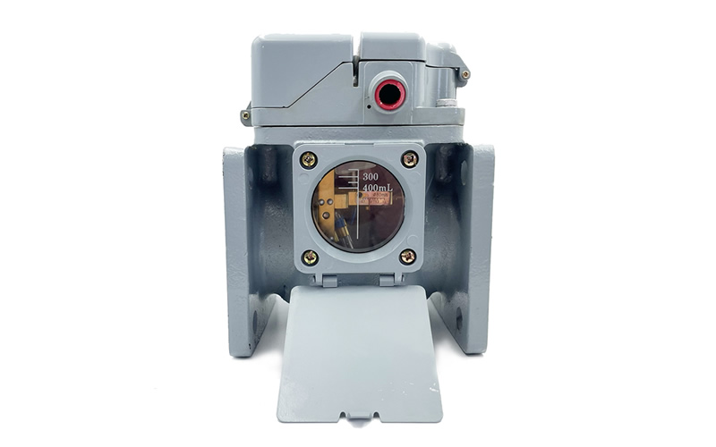

QJ SeriesGas Relay(hereinafter referred to as the relay), is an oil-immersed transformer used to protect the device, due to internal transformer failure and the decomposition of the oil gas or cause the oil flow surge, so that the relay contact action, connected to the designated gas circuit, and timely signal or automatically cut off the operation of the transformer.
Common Relay Models (Partial display Contact us for more).
QJ1-50 QJ1-50A QJ1-50A-TH QJ2-40 QJ3-40 QJ4-50 QJ4-50A QJ4-50A-TH QJ1-80 QJ1-80A QJ4-80 QJ4-80A QJ4-80A-TH
QJ1-80A-TH
Differences between QJ1 and QJ4 gas relays.
QJ1 type: mounting bolt hole with threads
QJ4 type: mounting bolt hole without threads
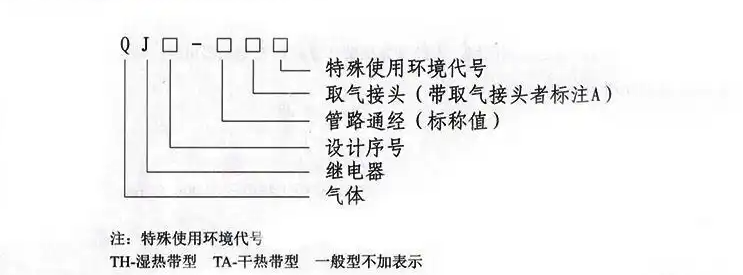
The meaning of other letters outside the QJ model number.
Rear label with A is with air box type
Rear label with TH is with rain cover type
Working Principle
When the transformer is working normally, the relay is filled with transformer oil, if the transformer is in operation, the
Minor faults, so that the transformer oil decomposition and the resulting gas will be gathered in the upper part of the relay, forcing the relay float down, when the float down to a certain limited position of the amount of gas reaches 250 ml, the magnet makes the signal contact turn on, send out an alarm signal.
If the transformer is leaking oil and the oil level is lowered, the same alarm signal will be issued. If a serious fault occurs inside the transformer, there will be a surge of oil, generating a flow of oil in the pipeline, impacting the gear plate movement of the relay. When the value of the flow rate of the gear plate movement reaches a certain limited position, the magnet makes contact with the contact, cut off all power supplies connected to the transformer.
Technical parameters:
Operating temperature -30℃~ +95℃Contact capacity AC 220V 0.3A COSΦ≤0.6
DC 220V 0.3A S≤5X10 -3S
Work Characteristics:
| norm | QJ-80 | QJ-50 |
| Oil speed setting range (m/s) | 0.7-1.5 | 0.6-1.2 |
| Gas aggregation quantity (ml) | 250~300 | |
If there are no special instructions; QJ-50 type flow rate setting value for (0.8 ± 0.05) m / s; QJ-80 type flow rate setting value for (1.0 ± 0.05) m / s
Sealing performance:
The relay is filled with transformer oil and pressurized with 200KPa at room temperature for 20 minutes without leakage.
Insulation properties:
| Test items | Between contacts of a contact | contact-to-ground | Between signal contact and trip contact |
| Withstand frequency voltage and time | 2000V/1min | 2000V/1min |
2000V/1min |
Seismic performance:
When the vibration frequency is 4~20Hz and the acceleration is 4g, the relay will not operate.
Installation and use
The relay is installed in the connecting pipeline between the transformer tank and the oil conservator, when installing, make the arrow on the relay point to the side of the oil conservator After installation, open the oil valve in the connecting pipeline, and at the same time, open the gas plug to discharge the gas, so that the relay is filled with the transformer oil, and close the gas plug tightly when the oil flows out of the gas plug.
After the installation is completed, press the probe (experimental test button), whether there is light gas and heavy gas signal output.
caveat
Newly shipped relays must have the relay core removed and the shipping tie-downs removed prior to installation and use.
The relay must be tested by a special test device before it is installed and used.
One side of the baffle is equipped with a spring, change the length of the spring, you can adjust the oil flow rate of the tripping contact action
Degree. Changing the position of the weight adjusts the amount of alarm gas. The rest of the components must not be moved arbitrarily.
When replacing or adding magnets and parts near the contacts, use non-conductive materials.
The magnet should not be subjected to violent vibration or placed in a strong magnetic field or in an environment exceeding 100℃ and below -40℃.
The contact shall not be dismantled or unloaded at will, especially the root lead shall not be bent arbitrarily to avoid damage.
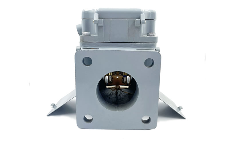
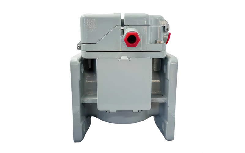
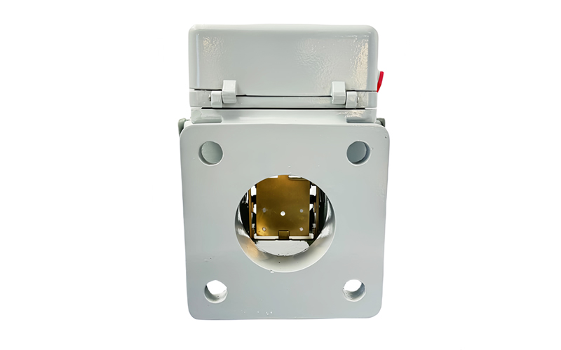
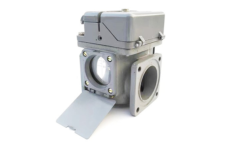
Structure, appearance and dimensions
| model number
type |
connection line
Connection (mm) |
L | Φ1 | Φ | d | H | A |
| QJ1-50 | 50 | 160 | 50 | 130 | M12 | 220 | 120 |
| QJ4-50 | 50 | 185 | 50 | 125 | Φ14 | 215 | 125 |
| QJ1-80 | 80 | 160 | 80 | 130 | M12 | 220 | 120 |
| QJ4-80 | 80 | 185 | 80 | 160 | Φ18 | 235 | 160 |
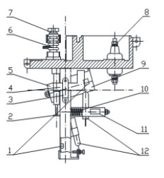
working schematic
1. magnet 2. heavy gas probe 3. toggle track 4. light gas toggle 5. heavy hammer 6. probe (experiment button) 7. bleeder valve 8. terminal block 9. float bowl 10 flow rate adjustment spring 11. flow rate scale 12 reed switch
*Before the transformer is shipped and operated, the reliability of light and heavy gas must be checked (press probe 6 to check whether there is a reliable signal output).

External Dimensions
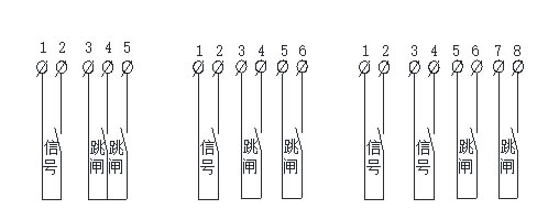
Wiring schematic
| serial number | Product Model | Tube length (mm) | Gas volume (ml) | Flow rate calibration range (m/s) | Reed contact characteristics |
| 1 | QJ4-25 |
25 |
200~250 |
1.0 |
Single signal, single trip |
| 2 | QJ4G-25 |
∕ |
single trip | ||
| 3 | QJ6-25 | Double tripping | |||
| 4 | QJ1-50 | 50 |
250~300 |
0.6 to 1.2 |
single signal Double tripping with common point |
| 5 | QJ1-80 | 80 | 0.7 to 1.5 | ||
| 6 | QJ2-50 | 50 | 0.6 to 1.2 | ||
| 7 | QJ2-80 | 80 | 0.7 to 1.5 | ||
| 8 | QJ3-50 | 50 | 0.6 to 1.2 | Single Signal Dual Independent Trip | |
| 9 | QJ3-80 | 80 | 0.7 to 1.5 | ||
| 10 | QJ4-50 | 50 | 0.6 to 1.2 | Single Signal, Double Trip with Common | |
| 11 | QJ4-80 | 80 | 0.7 to 1.5 | ||
| 12 | QJ5-50 | 50 | 0.6 to 1.2 |
Single Signal Dual Independent Trip |
|
| 13 | QJ5-80 | 80 | 0.7 to 1.5 | ||
| 14 | QJ6-50 | 50 | 0.6 to 1.2 | ||
| 15 | QJ6-80 | 80 | 0.7 to 1.5 | ||
| 16 | QJ7-50 | 50 | 0.6 to 1.2 | single signal
Double tripping with common point |
|
| 17 | QJ7-80 | 80 | 0.7 to 1.5 | ||
| 18 | QJ8-50 | 50 | 0.6 to 1.2 |
Dual Signal with Common Point Dual Trip with Common Point |
|
| 19 | QJ8-80 | 80 | 0.7 to 1.5 | ||
| 20 | QJ9-50 | 50 | 0.6 to 1.2 | ||
| 21 | QJ9-80 | 80 | 0.7 to 1.5 | ||
| 22 | QJ10-50 | 50 | 0.6 to 1.2 | single signal
Double tripping with common point |
|
| 23 | QJ10-80 | 80 | 0.7 to 1.5 | ||
| 24 | QJ11-50 | 50 | 0.6 to 1.2 |
Single Signal Dual Independent Trip |
|
| 25 | QJ11-80 | 80 | 0.7 to 1.5 | ||
| 26 | QJ12-50 | 50 | 0.6 to 1.2 | ||
| 27 | QJ12-80 | 80 | 0.7 to 1.5 | ||
| 28 | QJ13-50 | 50 | 0.6 to 1.2 | ||
| 29 | QJ13-80 | 80 | 0.7 to 1.5 | ||
| 30 | QJ14-50 | 50 | 0.6 to 1.2 | With common electric double signal
Double tripping with public power |
|
| 31 | QJ14-80 | 80 | 0.7 to 1.5 | ||
| 32 | QJ15-50 | 50 | 0.6 to 1.2 | Single Signal Dual Independent Trip | |
| 33 | QJ15-80 | 80 | 0.7 to 1.5 | ||
| 34 | QJ16-50 | 50 | 0.6 to 1.2 | Dual Signal with Common Point
Double tripping with common point |
|
| 35 | QJ16-80 | 80 | 0.7 to 1.5 | ||
| 36 | QJ17-50 | 50 | 0.6 to 1.2 |
Dual independent signal single trip |
|
| 37 | QJ17-80 | 80 | 0.7 to 1.5 | ||
| 38 | QJ18-50 | 50 | 0.6 to 1.2 | ||
| 39 | QJ18-80 | 80 | 0.7 to 1.5 | ||
| 40 | QJ19-50 | 50 | 0.6 to 1.2 | Dual independent signals
Dual independent tripping |
|
| 41 | QJ19-80 | 80 | 0.7 to 1.5 |