How to choose a dry-type transformer thermostat? Function comparison and wiring instructions
Date: March 28, 2026 09:01:46
- Dry-type transformer thermostatIt is a system that monitors the temperature of the windings, automatically controlsCooling FansA core protection device that starts and stops and signals an alarm or trip in case of over-temperature.
- There are many thermostat models, and the function suffix letter (D/E/F/G/I) determines the specific function configuration of the product, which should be checked against the actual demand one by one when selecting the model.
- The need for telecommunication, analog output, or core temperature monitoring are three key decision points for selection.
- Wiring is the most error-prone part of the thermostat before it is put into operation, and it should be operated in strict accordance with the wiring diagram attached to the product.
- InnoTech BWDKThe S201 series is a mainstream dry-change thermostat widely used today, supporting customization and multi-model combinations.
First, what is a dry-type transformer thermostat?
Dry-type transformer temperature controller, also known as dry-type transformer temperature controller, is specially designed for dry-type transformer winding temperature monitoring and control device. It collects the temperature of each phase of the winding in real time through the PT100 platinum resistance temperature sensor embedded in the three-phase winding of the transformer, and automatically completes the following control actions according to the temperature value: fan start-stop control, over-temperature alarm, over-temperature trip protection, as well as the local display and remote transmission of temperature data.
Dry-type transformer without insulating oil as a heat dissipation medium, the winding temperature is the most direct, the most critical parameter to judge its operating status. Once the winding temperature exceeds the upper limit of the insulation grade, the aging rate of the insulation material will be exponentially accelerated, and in serious cases, even triggered the winding burned out. Therefore, the temperature controller for dry-type transformer is not an optional accessory, but an essential safety device.
Second, what are the core functions of the dry-type transformer thermostat?
Different models of thermostats have different extended configurations on top of the basic functions, and understanding the meaning of each function is a prerequisite for correct selection. The following is a description of the main function modules:
Three-phase circuit display and maximum value display
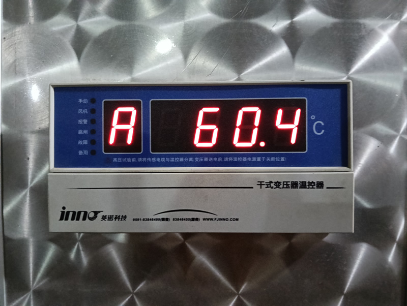
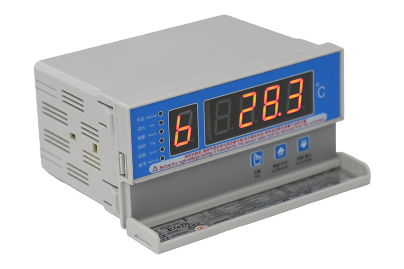
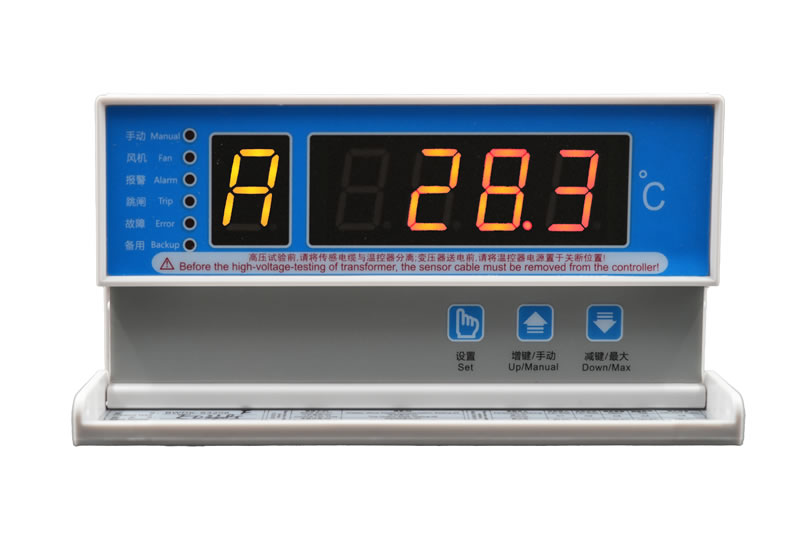
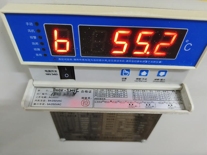
The thermostat displays the real-time temperature of A, B and C phases in turn, and can be switched to display the highest temperature value of the current three phases. Operation and maintenance personnel can read the temperature status of the most dangerous point directly through the panel, without the need to check phase by phase.
Automatic/manual start/stop control of fans
When the winding temperature reaches the set fan start threshold, the temperature controller automatically outputs a signal to start the cooling fan; the temperature drops to the shutdown threshold and then automatically stops. At the same time, it supports manual start-stop, which is convenient for debugging and emergency operation.
Over-temperature alarm and over-temperature trip
When the temperature exceeds the alarm setting value, the temperature controller triggers sound and light alarm, prompting the operation and maintenance personnel to pay attention to; if the temperature rises further than the trip setting value, the temperature controller outputs a trip signal, triggering the circuit breaker to break, and forcibly cut off the power supply of the transformer, to protect the equipment from more serious damage. Alarm and trip temperature value can be set independently.
Fault alarm (sensor disconnection/short circuit detection)
When the temperature sensor is disconnected or short-circuited, the thermostat is able to automatically recognize and send out a fault alarm signal, avoiding the monitoring blind spot and misoperation caused by the sensor failure.
"black box" function
The thermostat has a built-in historical data recording function, which can store the temperature peaks and alarm event records in the recent period. After an abnormality occurs, maintenance personnel can restore the temperature change process before the accident by querying the black box data, which provides the basis for fault analysis.
Fan timed excitation function
For long-term low load operation, fan rarely automatic start of the transformer, the thermostat can automatically start the fan periodically for a short period of time, to prevent the fan due to long-term stoppage caused by bearing corrosion jamming, to ensure that the fan in the real need to be able to operate normally.
Simulation test function
It can simulate alarm triggering and tripping action without actual warming up, and is used in the installation and commissioning stage to verify whether the wiring is correct and the alarm circuit is smooth.
Digital Compensation Function
For measurement deviations caused by individual differences in different sensors or installation positions, digital corrections can be made through software parameters to improve measurement accuracy.
Third, what does the suffix letter of the thermostat model represent?
In the case of the Inotera BWDK-S201 series, for example, the letters of the function suffix in the model number are the key to differentiate the configuration of each model. Understanding the meaning of these letters is a shortcut to quickly complete the selection.
| model number | Functional Description | Applicable Scenarios |
|---|---|---|
| BWDK-S201D | Standard basic type: three-phase circuit display, fan automatic/manual control, over-temperature alarm, over-temperature trip, fault alarm, black box, fan timing excitation, analog test, digital compensation, cabinet door opening alarm | General applications that do not require remote transmission or analog outputs |
| BWDK-S201E | Adds three or four independent 4-20mA analog current outputs to the D model. | Where temperature signals need to be connected to a PLC, DCS or dispatch system |
| BWDK-S201F | Adds RS485/RS232 serial communication to the D model. | Need to access SCADA, intelligent operation and maintenance platform or support Modbus protocol systems |
| BWDK-S201G | On the basis of D type, add one way to measure and control the ambient temperature of the machine room. | Where the ambient temperature of the transformer room needs to be monitored at the same time |
| BWDK-S201I | On the basis of D-type, add a transformer core temperature measurement and alarm. | Where independent core temperature monitoring is required |
| BWDK-S201EF | Simultaneous 4 to 20 mA analog output (E) and RS485 communication function (F) | Integrated systems requiring both analog access and digital communication |
Function codes can be freely combined, e.g. EFG with analog output, communication and ambient temperature monitoring. For special requirements such as Ethernet communication, Profibus, fiber optic temperature measurement, etc., we can also contact the manufacturer for custom development.
Fourth, how to choose the right model according to the actual needs?
The core logic of the selection is: first determine the basic requirements, and then check the box item by item according to the extended functionality. The following are a few typical scenarios of selection recommendations:
Scenario 1: Ordinary factory power distribution room, no monitoring system access requirements
选 BWDK-S201DThe standard basic model already covers all protection and control functions without additional extensions and offers the best price/performance ratio.
Scenario 2: Temperature data needs to be connected to the plant PLC or DCS system.
选 BWDK-S201EThe 4-20mA analog output can be directly connected to most PLC analog input modules without additional conversion devices.
Scenario 3: Substation needs to be connected to intelligent operation and maintenance platform or dispatching system (Modbus protocol)
选 BWDK-S201FThe RS485 communication interface supports Modbus RTU protocol, which can be directly connected with mainstream SCADA and intelligent operation and maintenance systems.
Scenario 4: Unattended substation, both analog and digital communication dual-channel outputs are needed at the same time
选 BWDK-S201EFThe two signal outputs are coexisting, which can be collected by the local PLC and read by the remote dispatching system, making the redundant configuration more reliable.
Scenario 5: Additional core temperature monitoring required
contain only I Function code models, on the basis of three-phase winding temperature monitoring, increase the core temperature independent monitoring channel, suitable for large-capacity transformers or high load occasions that are sensitive to core heating.
V. BWDK-S201 Main Technical Parameters
The following are the core technical specifications of Inotera BWDK-S201 series thermostats for selection and engineering design reference:
| Parameter items | parameter value |
|---|---|
| operating voltage | AC 220V (+10%, -15%) |
| operating frequency | 50Hz or 60Hz (±2Hz) |
| Temperature measurement range | -30.0℃~+240.0℃ |
| Measurement accuracy | ±1%FS (thermostat class 0.5, sensor class B) |
| Display resolution | 0.1°C |
| Fan Output Capacity | 9A / 250VAC |
| Control output capacity | 5A / 250VAC; 5A / 30VDC (resistive) |
| Thermostat power consumption | ≤8W |
| environmental temperature | -20℃ ~ +55℃ |
| Environmental humidity | <95% (25°C) |
| Exterior Dimensions | 160mm × 80mm × 120mm |
| Panel cutout size | 153mm × 77mm |
| production standard | JB/T 7631-2016 "electronic temperature controller for transformer" industry standard |
| Certification Standards | ISO 9001:2016 International Quality Management System Certification |
| Electromagnetic compatibility standards | iec 61000-4:1995; gb/t 17626-2008 |
Six, thermostat installation and wiring need to pay attention to what?
The installation and wiring of the thermostat is the most critical part before commissioning, and also the place where mistakes are most likely to be made. The following are the main precautions:
Installation
BWDK-S201 adopts panel embedded mounting, you need to open the embedded holes on the transformer box or control box panel according to the hole size (153mm × 77mm), push the thermostat in from the front and fix it with the supplied clips or mounting brackets. After the installation is completed, make sure the panel fits tightly without loosening.
Sensor Wiring
Three-phase winding PT100 sensor terminals are usually labeled as A, B, C corresponding to the sensor interface, need to be connected according to the terminal number of the wiring diagram attached to the product one by one corresponding connection, not mixed. Sensor leads should be shielded wire, and keep a distance from strong electric lines to avoid electromagnetic interference affecting the measurement accuracy.
Fan control circuit wiring
The fan output terminal capacity is 9A/250VAC, which can directly drive the cooling fan with rated current within this range. If the fan power is larger, it is necessary to extend the driving capacity through the AC contactor, the thermostat only provides control signals, not directly carrying the fan main circuit current.
Alarm and trip circuit wiring
The over-temperature alarm and over-temperature trip correspond to independent relay output contacts, and it is necessary to distinguish between normally open (NO) and normally closed (NC) contacts when wiring. The trip circuit is usually connected to the shunt release of the circuit breaker, make sure that the polarity and circuit logic are correct before powering on the test.
4-20mA and RS485 Extended Function Wiring
E-type analog output according to the current loop two-wire or four-wire wiring, pay attention to distinguish between positive and negative poles.F-type RS485 communication wiring should pay attention to the A/B signal line polarity, the end of the bus is recommended to add a 120 Ω termination resistor, more than one device networking, each unit needs to be set up a unique communication address, to avoid the address conflict caused by communication failure.
Pre-commissioning verification
Once the wiring is complete, use the thermostat'sSimulation test functionVerify one by one whether the fan start/stop, alarm output and trip output circuits operate normally, and confirm that there is no error before officially putting into operation. Do not skip the debugging steps directly into operation, to avoid the real over-temperature accident only to find the wiring error.
Seven, the thermostat common faults and processing methods
| fault phenomenon | Possible causes | Recommendations for handling |
|---|---|---|
| No display or abnormal display | Abnormal supply voltage, loose power cord | Check the AC 220V power supply circuit and make sure the power cord is firmly connected. |
| Displays "Disconnected" or "Trouble" alarms | PT100 sensor broken wire or poor contact | Check whether the sensor terminals are loose, use a multimeter to measure whether the sensor resistance value is normal (about 100Ω at 0℃) |
| Temperature display is significantly high or low | Sensors are mounted in the wrong position, have poor contact or require digital compensation | Check that the sensor is not tightly attached to the winding and correct it using the digital compensation function |
| Fan does not start | Fan control circuit disconnection, contactor failure, or temperature not reaching the start-up threshold | Use the analog test function to force the trigger of the fan output, and troubleshoot the control circuit and contactor status. |
| Over-temperature alarm but no trip | Incorrectly wired trip circuits or high trip temperature settings. | Verify the trip circuit terminal wiring and confirm that the trip temperature setting value is reasonable. |
| No data for RS485 communication | Communication address conflict, baud rate mismatch, or reversed A/B polarity. | Verify communication address and baud rate settings, check A/B line polarity, and add termination resistor at the end. |
Eight, why choose Inotera dry-type transformer thermostat?
Inotonda BWDK-S201 series dry-type transformer temperature controller is independently developed and produced in strict accordance with JB/T 7631-2016 industry standards, passed ISO 9001:2016 quality management system certification, and has accumulated a large number of application cases in many domestic transformer manufacturers and power engineering projects.
Comprehensive function coverage and flexible model combination
From the basic type D to the extended type with communication, analog, and core temperature, the function codes can be freely combined so that the user can accurately match the actual requirements without paying for unneeded functions or compromising system integration due to missing functions.
Support customization to meet special needs
For projects with special requirements such as Ethernet communication, Profibus, fiber optic temperature measurement, multi-channel temperature acquisition, etc., Inotera can provide customized development services to expand the functionality on the basis of standard products and shorten the project implementation cycle.
Complete supporting products, one-stop supply
Inotera also provides matching dry-type transformer cooling fan (GFDD top blowing type, GFD side blowing type), PHM 300U intelligent monitoring device and other series of products, thermostat and fan, monitoring system can be purchased as a whole package to reduce the communication costs of coordination between multiple parties.
If you are selecting a thermostat for a dry-type transformer, welcome to contact Innotrans, provide the transformer capacity, voltage level and monitoring system interface requirements, you can get professional selection advice and quotation.
statement denying or limiting responsibility
The content of this article is for general reference only, aims to introduce the dry-type transformer thermostat selection ideas, functional description and wiring points, does not constitute the only basis for any project implementation or procurement decisions. The technical parameters involved in this article to the official product page information of InnoTech shall prevail, the actual specifications may vary due to product batch or customization requirements. The installation and wiring of the thermostat must be operated by qualified electrical professionals, and the accompanying instruction manual shall prevail. The author and publisher of this article shall not be liable for any direct or indirect loss arising from reference to the contents of this article.