

What is transformer remote oil level meter? Working principle, technical parameters and selection guide
Date: March 20, 2026 18:00:49
- transformersoil level meterIt is a special instrument for monitoring the level of insulating oil in the oil storage cabinet, and is an indispensable safety accessory for oil-immersed transformers.
- Abnormal oil level (too high or too low) can cause transformer failure, timely warning is the key to ensure the safe operation of equipment.
- Remote oil level gauge in the local indication of the basis, add 4-20mA analog output, realize the long-distance real-time monitoring.
- When selecting the model, it is necessary to consider the size of the oil conservator, the installation method, the protection level and the need for remote transmission function.
- YZF3-200 remote oil level gauge is designed for fully sealed large and medium-sized transformers, supporting customization, suitable for all kinds of severe working conditions.
First, what is the transformer oil level meter? What is its role?
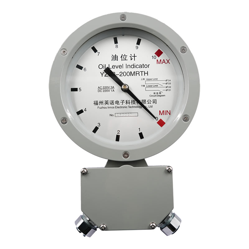
Transformer oil level meter is installed on the oil storage cabinet of oil-immersed transformer, used for real-time monitoring of the level of insulating oil in the oil storage cabinet. It through the float or telescopic rod sensing oil level changes, the oil level to pointer or digital visual display, and in the oil level exceeds the normal range when the alarm signal.
Oil-immersed transformers rely on insulating oil for insulation and heat dissipation. The oil conservator acts as an oil regulator, automatically compensating the oil level as the transformer load and temperature change. The central role of the oil level meter is to continuously monitor this dynamic process and to ensure that the transformer always operates within a safe oil level.
For the oil level meter equipped with remote transmission function, the oil level signal can also be converted into standard 4-20mA analog quantity and transmitted to the remote monitoring system or dispatching center via cable, realizing remote oil level monitoring and early warning of unmanned places, which greatly improves the efficiency of operation and maintenance.
Second, transformer oil level is too low or too high will have what harm?
Many operation and maintenance personnel think that the oil level meter is only an auxiliary instrument, in fact, the oil level abnormality is one of the important precursors of transformer failure, which should not be ignored.
The dangers of low oil levels
When the oil level in the oil conservator continues to fall, it means that the transformer may have leakage or sealing failure. Insufficient oil will directly lead to the core and winding insulation and heat dissipation ability to decline, lightly accelerate the insulation aging, heavy trigger winding overheating or even breakdown discharge. Serious oil leakage may also lead to air ingress into the oil conservator, introducing moisture and oxygen, accelerating oil deterioration and causing irreversible damage to the transformer insulation system.
The dangers of high oil levels
Abnormally high oil level is usually related to transformer overload, high oil temperature or sealing system failure. Excessive oil level will reduce the gas space in the oil conservator, resulting in increased oil pressure, which may cause severepressure relief valveaction or even oil tank deformation. In addition, high oil temperature itself is an accelerating factor for insulation aging, and a long period of time at a high oil level means that the equipment is operating under high load or abnormal environment.
Therefore, the oil level meter is not only a "look at the amount of oil" tool, but also an important observation window of the transformer operation status. Once found that the oil level abnormal alarm, should immediately investigate the cause, can not be taken lightly.
Third, what are the common types of oil level gauges?
The type of transformer oil level meter on the market is not complicated, mainly according to the measurement principle and function is divided into the following categories, each has its own application scene.
| typology | Measuring principle | Display mode | Whether to support remote transmission | Applicable Scenarios |
|---|---|---|---|---|
| Pointer Float Oil Level Gauge | Float ball with the oil level up and down to drive the pointer rotation | Indicator dial in situ | Optional (4-20mA) | Large and medium-sized oil-immersed transformers |
| Pointer type telescopic rod oil level gauge | Telescopic rod senses changes in oil level | Indicator dial in situ | Optional | Small transformers or space-constrained applications |
| Magnetic Oil Level Gauge | The magnetic float rises and falls with the oil level and drives the magnetic flap display. | Red and Green Magnetic Flip Chart Local Display | Optional | Occasions where visual color blocking is required |
| Remote Digital Oil Level Gauge | Signal transmitter added to pointer type | Local pointer + remote digital display | ✅ Standard 4-20mA | Unattended stations, centralized monitoring systems |
In practical engineering.Pointer Float Remote Oil Level GaugeYZF3-200 is the most widely used type at present, taking into account the needs of both local display and remote monitoring, and its structure is mature, reliable and easy to maintain, YZF3-200 belongs to this kind of products.
Four, pointer type remote oil level meter working principle
Understanding the working principle helps operation and maintenance personnel to make accurate judgments during daily inspection and troubleshooting. The working process of pointer-type remote oil level gauge can be divided into two links: mechanical conduction and electrical signal output.
mechanical conduction link
The float mounted in the oil reservoir floats up and down with the level of the oil, and this displacement is transmitted to the rotation mechanism of the oil level gauge through the pendulum. The rotating mechanism transmits the movement to the pointer shaft outside the dial via a magnetic coupling, which drives the pointer to indicate the current oil level on the dial. Due to the magnetic coupling drive, the oil level gauge is completely sealed internally so that no insulating oil can leak out through the drive mechanism.
Alarm signal output
When the oil level rises to the high oil level alarm scale or lowers to the low oil level alarm scale, the magnet attracts the corresponding reed switch, triggering an electrical alarm signal to notify the operation and maintenance personnel to handle the situation in time.
Remote analog output
Models equipped with remote transmission function (e.g. YZF3-200M) have a built-in signal transmitter, which converts the swing angle of the pointer into 4-20mA standard current signal output in real time. Oil level meter dial scale 0 corresponds to 4mA, scale 10 corresponds to 20mA, the middle position is proportional to the linear output, the back-end monitoring system can be based on the restoration of the real-time oil level value, to achieve continuous remote monitoring.
V. Remote Oil Level Gauge vs Local Oil Level Gauge: What is the difference?
At the procurement stage, users are often faced with the problem of choosing between in situ oil level meters and remote oil level meters. The difference in functionality between the two directly affects the operation and maintenance mode and the experience of using them.
| comparison dimension | In-situ oil level gauge | Remote oil level meter (e.g. YZF3-200M) |
|---|---|---|
| Display mode | Dial hands read in situ | Local pointer + remote digital display or monitoring system |
| Real-time monitoring | Requires regular manual readings | 24-hour continuous automatic acquisition without human intervention |
| Abnormal Alarms | In-situ audible and visual alarms | Local Alarm + Remote System Linkage Alarms |
| signal output | Switching Alarm Contacts Only | Switching Alarm Contact + 4-20mA Analog |
| Access to monitoring systems | unsupported | Support, access to SCADA, dispatching system |
| Applicable places | Manned and easy to inspect premises | Unattended stations, remote centralized monitoring sites |
| Installation complexity | Simple, mechanical installation only | Slightly higher, requires additional signal cable routing |
| product costs | relatively low | Slightly higher (add transmitter module) |
Overall, for substations with centralized monitoring needs or unattendedRemote oil level meter is a better choiceThe system is designed to provide a one-time investment that is slightly higher, but saves on manual inspection costs and significantly improves anomaly response time.
Six, YZF3-200 remote oil level meter core technical parameters
The following are the main technical specifications of YZF3-200 remote oil level meter for selection reference:
| Parameter items | parameter value |
|---|---|
| Product Model | YZF3-200 / YZF3-200M (with 4-20mA output) |
| Dial Diameter | Ø 200mm |
| Pointer swing angle | 270° (dial scale 0 to 10 digits) |
| Pendulum start position | Horizontal start, mounted under the side wall of the oil conservator |
| Pendulum mounting angle | 45° |
| warning error | Less than full disk 2.5% |
| Alarm contact capacity | AC 220V / 1A; DC 220V / 0.3A |
| analog output | 4-20mA (YZF3-200M type) |
| Operating Voltage (Transmitter) | Recommended DC 24V, not to exceed 35V |
| Industrial frequency withstand voltage | 2kV for 1min |
| environmental temperature | -25℃ ~ +40℃ |
| Ambient relative humidity | Not greater than 90% (20°C) |
| Sealing performance | 300kPa, 20min No leakage |
| protection class | IP55 |
| Outer diameter of mounting flange | Ø 156mm |
| Mounting hole diameter | Ø 127mm (6-M10 bolts) |
| Oil Reservoir Opening Dimensions | Ø 100mm |
| Customized Support | Flange size and pendulum length can be customized. |
The pendulum length L is calculated as:L = 1.414 (D - 200)D is the diameter of the oil conservator (mm). Users are recommended to measure the actual size of the oil conservator before purchasing to ensure that the pendulum length matches the installation space.
VII. What do I need to pay attention to when installing an oil level gauge?
Correct installation is the basis for long-term accurate operation of the oil level gauge. The following are key considerations before installation and commissioning:
Pre-installation inspection
Before installation, the float and pendulum should be connected completely, check whether the pointer rotation is flexible and no loosening; manually dial the float pendulum to the lowest and highest position, confirm that the pointer reaches the corresponding red alarm area and the alarm signal is triggered normally; check whether the glass of the dial is intact, and whether there is any breakage or deformation of the float.
Installation operations
When installing, first extend the float part into the inner cavity of the oil conservator, and then fasten the oil level meter to the mounting flange with bolts. The mounting flange is to be provided by the user and must match the mounting holes of YZF3-200 (Ø 127mm, 6-M10). After the installation, check whether the sealing gasket is pressed tightly to ensure that there is no risk of leakage.
Wiring Precautions
The remote transmission model (YZF3-200M) needs to be connected with a signal line to the back-end display instrument or monitoring system. The signal line should be shielded cable, avoid parallel laying with strong electric lines to prevent electromagnetic interference. The working voltage of the transmitter is recommended to be DC 24V, and it is forbidden to exceed 35V, otherwise the transmitter module may be damaged. When wiring in two-wire system, D4 and D5 terminals do not need to be wired, D7 connects to the 7 end of the digital display, and D6 connects to the 12 end of the digital display.
Precautions for use
Oil level meter is a precision instrument, non-essential not to disassemble the internal drive mechanism; the use of the environment should not be violent vibration or strong impact; the measured liquid level should not fluctuate violently, otherwise affect the accuracy of the indication. If transported with the oil storage cabinet as a whole, the float pendulum part should be fixed in advance, and it is recommended to install the float on site before leaving the factory as a whole.
Eight, the oil level meter common faults and troubleshooting methods
The following are the most commonly encountered types of oil level meter faults in operation and maintenance and the corresponding troubleshooting ideas for reference.
| fault phenomenon | Possible causes | Troubleshooting and treatment recommendations |
|---|---|---|
| Pointer not moving or stuck | The transmission mechanism is jammed, the float is stuck by a foreign object. | After power outage, check whether the pendulum and float are stuck by debris, and check whether the gear set is corroded |
| Pointer indication does not match actual oil level | Pendulum length mismatch, float damage oil intake | Verify that the length of the pendulum and the diameter of the oil conservator are in accordance with the formula; check whether the float is broken and oil ingress leads to sinking |
| Frequent misoperation of the oil level alarm | Reed switch position offset, vibration interference | Check the position of the alarm magnet relative to the reed switch, and confirm that there is no abnormal source of vibration in the installation environment. |
| Abnormal 4-20mA signal or no output | Abnormal transmitter power supply voltage, loose wiring | Check whether the supply voltage is within the range of 24V, check whether the D6/D7 terminals are firm, and measure the output circuit with a multimeter. |
| Oil Leakage from Oil Level Gauge | Deteriorated sealing gaskets, loose mounting flange bolts | Tighten mounting flange bolts after power outage, replace sealing gaskets if necessary, and redo sealing test |
| Fogged or blurred dial glass | Water and moisture inside | Check the sealing condition of the meter head, replace the moisture-proof desiccant or contact the manufacturer for maintenance treatment |
A special reminder is that oil level gauges are precision instruments.It is not recommended to disassemble the internal mechanism by yourself after a malfunction.The manufacturer should be contacted in a timely manner to avoid expanding the scope of the failure due to improper operation.
Nine, how to choose the right model according to the size of the oil storage cabinet?
The model selection of the oil level gauge is directly related to the diameter and installation position of the oil storage cabinet. Improper selection will lead to insufficient float travel or interference between the pendulum and the cabinet wall, affecting normal use. The following is the basic idea of model selection:
Step 1: Confirm transformer type and oil conservator size
Measure the inner diameter of the oil conservator, D (mm), which is the central basis for calculating the length of the pendulum. Also confirm whether the oil conservator is of fully sealed or open construction, and whether it is mounted on the sidewall or the top.
Step 2: Calculate the required pendulum length
For the YZF3-200 model, the formula for calculating the length of the pendulum is:
L = 1.414 × (D - 200) mm
For example, if the inner diameter of the oil conservator is D = 500mm, then L = 1.414 × 300 ≈ 424mm. If the calculation result is out of the range of the standard pendulum, you can contact INNOTEC for customization.
Step 3: Confirm whether you need the remote transmission function
If you need to connect to a monitoring system or realize remote oil level monitoring, choose the model with M suffix (YZF3-200M), which includes 4-20mA analog output. For local display and alarm only, choose the standard YZF3-200.
Step 4: Confirm mounting flange size
YZF3-200 standard flange outer diameter is Ø 156mm, mounting aperture Ø 127mm, using 6 M10 bolts fixed. If the original opening or flange size is different, please inform the manufacturer in advance to customize according to the actual size.
Why choose Inotera YZF3-200 Remote Oil Level Gauge?
In the selection of accessories for oil-immersed transformers, the oil level meter is small in size, but its reliability is directly related to the safe operation of the transformer. With the following points, YZF3-200 remote oil level meter has gained the long-term trust of many power users.
Highly reliable sealing structure
YZF3-200 adopts magnetic coupling drive mechanism, completely sealing and isolating between meter head and oil storage cabinet, no leakage under 300kPa pressure for 20 minutes, and the protection level reaches IP55, which is able to run stably under the bad working conditions of high humidity and dusty outdoor.
Mature and stable telecommunication function
YZF3-200M model built-in high-precision signal transmitter, 4-20mA analog output linearity is good, the alarm error is less than the full disk 2.5%, signal stability and reliability, can be directly accessed to all kinds of monitoring platforms, SCADA systems or digital display instrumentation, without the need for secondary conversion.
Flexible customization for a wide range of working conditions
Flange outer diameter, mounting holes, pendulum length can be customized according to the user's actual oil storage cabinet size, to solve the old transformer transformation of the original hole size is not standard common problems, the scope of application is wider.
Manufacturer direct supply, service guarantee in place
As a manufacturer of oil level meter, Innotongda provides the whole process service from selection consultation, product supply to installation and technical support. For detailed technical drawings, customized pendulum length quotes, or bulk purchasing solutions, please contact Innotranslate technical engineers directly.
statement denying or limiting responsibility
The content of this article is for general reference only, aims to introduce the basics of transformer oil level meter, working principle and selection of key points, does not constitute the only basis for the implementation of any project or procurement decisions. The technical parameters listed in this article are subject to the official product page of InnoTech, and the actual specifications may vary due to model or customization requirements. Specific projects should be evaluated and confirmed by professional and technical personnel in conjunction with site conditions. The author and publisher of this article shall not be liable for any direct or indirect loss arising from reference to the content of this article.