
Where is the transformer's fan switch located? How is the fan switch usually remotely controlled on large transformers?
Date: July 21, 2025 10:25:50
The switching position of the transformer fan depends on the specific model and installation, but there are generally the following common positions:
-
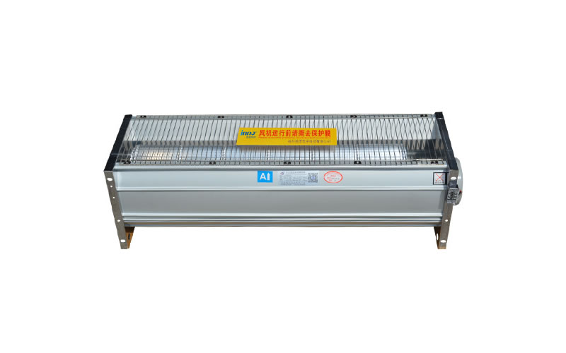
Inside the control cabinet: Most dry-type transformers will have the fan control switch integrated into theTransformer control cabinetmaybeLow-voltage distribution cabinetsInside, there is usually a "manual/automatic" selector switch (SAC) and start/stop buttons (e.g. SF1, SF2).
-
control panel: Some transformers (e.g., furnace transformers) are equipped with acontrol panelThe fan switch is integrated directly into this panel for easy in-place operation.
-
Bottom of the cabinet: Some fans mounted in transformer cabinets may have switches and contactors located in theBottom of cabinet frontThe system is easy to access for maintenance and emergency operations.
-
remote control room: For large or distributed systems, the fan switch may be located in theremote control roommaybeCentralized control panel in the fire control roomon, connected by secondary control lines.
If you are using theSchneider Trihal dry-type transformersThe fan itself is mounted on the bottom two side rails, but the control switch is not in the fan body, but in the control cabinet.
For exact location, it is recommended to check the transformer supplied with theControl Circuit DiagrammaybeCabinet Marking, or contact the equipment manufacturer for specific wiring diagrams.
How do large transformers typically control fan switching remotely?
for large transformersRemote control of fansThe core methods include the following, which are usually realized by a set of **"Local Controller + Remote Control Platform" **architecture:
✅ 1. Remote control based on SCADA/collective control system
-
implementation method: The turbine control loop is connected to a remote I/O module via a substation centralized control system or an energy management system (EMS/SCADA).
-
control logic::
-
Remotely issue "remote close/remote split" commands;
-
The fan is started and stopped via intermediate relays and contactors;
-
Supports "auto/manual" switching with status feedback.
-
-
communications protocol: Modbus TCP, IEC 60870-5-104, Profibus, etc. are commonly used.
✅ 2. Intelligent Transformer Monitoring System (Cloud Platform)
-
implementation method: Fan control accessIoT terminals (e.g. LoRa, 4G DTU)The data is uploaded to a cloud platform (e.g., AliCloud, Huawei Cloud Energy Management).
-
Functional Features::
-
Real-time view of turbine operating status;
-
Remotely start and stop the fan;
-
Automatically starts and stops the fan according to the oil temperature and load rate;
-
Fault alarm and history query.
-
-
typical application: Data centers, industrial parks, dry-type transformers above 110kV.
✅ 3. Local Controller + Wireless Remote Terminal
-
System Components::
-
local controller: Installation next to the transformer, including PLC or microcontroller;
-
remote terminal: Operations and maintenance personnel give instructions remotely via handheld terminals or computers;
-
communication method: Wireless (e.g. ZigBee, LoRa, 4G).
-
-
dominance: No wiring required, suitable for remote substations or temporary deployment scenarios.
✅ 4. Group control and rotation control (multiple turbines)
-
implementation method: Through PLC or DSP controller, realize multiple wind turbines'Rotation operation, failover.;
-
remote function::
-
Set the rotation strategy remotely from the monitoring room;
-
View each turbine's operating hours and fault logs;
-
Remote forced start/stop of a turbine.
-
🔧 To summarize: a generic process for remotely controlling a fan switch
| move | instructions |
|---|---|
| ① Status Acquisition | Temperature, current, fan operation status, etc. are collected by sensors. |
| ② Local judgment | The local controller determines whether the fan needs to be activated (automatic mode) |
| ③ Remote command | Operation and maintenance personnel through the centralized control system or cloud platform to send start-stop instructions |
| ④ Execute the action | Local controller drives contactor closure/disconnection, fan start/stop |
| ⑤ Status feedback | Fan status is transmitted back to the remote platform for monitoring and recording. |
If deployment or retrofitting is required, it is recommended that priority be given toModbus TCP + SCADAmaybeIoT Cloud PlatformPrograms that are compatible and scalable.