bwr transformer winding thermometer type
Date: July 22, 2025 10:37:36
| BWR-4 |
| BWR-4AD |
| BWR-4D |
| BWR-4DD |
| BWR-6 |
| BWR-6AD |
| BWR-6D |
| BWR-6DD |
| bwr-06 |
| bwr2-04 |
| bwr2-06 |
| BWR-04 |
| BWR2-04AA |
| BWR-04JJ |
| BWR-04Y1 |
| BWR2-04A |
| Transformer temperature controller bwr-04j |
| Transformer winding thermostat bwr2 |
| Transformer Winding Thermostat BWR2-04AJ TH |
| Transformer winding thermostat bwr |
| bwr transformer winding temperature control |
| Transformer winding thermostat bwr |
| BWR-04C(TH) |
| BWR-04J |
| BWR2-04AJTH |
| bwr 04 transformer |
| BWR-04 Transformer |
| Transformer temperature BWR |
| Transformer temperature bwr |
| BWR-04 Transformer Supply |
| Transformer bwr-04d |
| BWR-04 Transformer Ordering |
| Transformer winding thermometer bwr |
| bwr transformer winding thermometer |
| Transformer thermometers bwr and bws |
| BWR-04 Transformer Manufacturer |
| bwr-04 transformer winding oil temperature meter |
| Transformer Winding Thermostat BWR-4 |
| Transformer winding thermometer bwr-06 |
| BWR-4D Thermostat Transformer |
| bwr-04 transformer winding thermometer |
| Transformer winding thermostat bwr-04a |
| Transformer winding temperature gauge BWR I 04 |
| bwr-04x transformer winding thermostat |
| bwr-04yj transformer winding thermostat |
| bwr-04j(th) transformer winding thermostat |
| Transformer winding thermostat bwr-04yj(th |
| Transformer Winding Thermostat BWR-06J TH |
| Transformer Winding Thermostat BWR I 06J |
| Winding thermostat for transformer bwr-04j |
| bwr-04a transformer oil level thermometer |
| BWR_04D Transformer Winding Thermometer |
| Transformer bwr-04d thermostat ct for what? |
| Transformer winding thermometer BWR a o4JJ |
| Transformer winding thermostat bwr-04 internal structure diagram |
| bwr2-04a transformer winding thermometer manual |
| Winding temperature bwr |
| bwr winding temperature |
| bwr temperature gauge |
| bwr-6 temperature |
| BWR Thermometer |
| Hengren temperature measurement and control BWR |
| bwr winding thermometer |
| Winding temperature gauge BWR |
| bwr temperature controller |
| bwr04aj temperature |
| bwr 04 winding thermometer |
| bwr-04 thermometer |
| bwr-04y operation temperature |
| Bwr-04 temperature gauge |
| bwr z temperature transmitter working principle |
| Fujian bwr thermometer |
| bwr-6 thermometer |
| bwr series resistance thermometer |
| BWR 04 Temperature Controller |
| Temperature gauge bwr-906 |
| bwr04 winding thermometer |
| Temperature controller bwr-04 |
| BWR04 Winding Temperature Official Website |
| bwr-04 winding thermometer |
| Winding thermometer bwr i6 |
| bwr-cy winding thermometer |
| Temperature measurement and control bwr-04a |
| bwr-6 winding thermometer |
| Winding thermometer bwr-04b |
| bwr-04 temperature controller |
| BWR 04 Winding Temperature Controller |
| Winding thermometer bwr-04 |
| How to adjust the temperature of bwr-04j |
| bwr04iii temperature gauge |
| bwr-04a thermometer |
| Thermometer bwr804a |
| bwr-04 winding temperature gauge |
| Temperature Controller bwr-4dd |
| BWR-04AD Winding Thermometer |
| bwr-04yth temperature gauge parameters |
| Winding thermometer bwr04b |
| Winding temperature controller bwr-04 |
| BWR-04III Thermometer |
| bwr04 winding temperature controller |
| BWR-04Y Winding Thermometer |
| BWR 04J Winding Temperature Controller |
| winding thermometer bwr 906l9 |
| bwr-04 temperature controller error correction |
| How to wire the BWR 04 winding temperature controller |
| bwr-04a winding temperature controller |
| BWR 04AJ Winding Temperature Controller |
| bwr winding thermometer two-color pointer meaning |
| bwr-4 thermometer instruction manual |
| Main transformer winding temperature controller bwr04 |
| bwr-04 temperature controller manual |
| bwr-6 winding thermometer manual |
| Principle of main transformer BWR04J winding thermometer |
| BWR-04Y winding thermometer wiring diagram |
| bwr04a winding temperature instruction manual |
| Winding temperature controller bwr-04d1ii |
| Thermometer bwr04y manual |
| bwr-04y(th) winding thermometer instructions |
| BWR-04 Winding Temperature Meter Instruction Manual |
| Temperature Controller bwr-4dd Leader Official Website |
| bwr-04j(th) winding thermometer instruction manual |
| BWR-4/BWR-04 |
| bwr-4ad/bwr-04ad |
| bwr-4ad/ye/bwr-04ad/ye |
| BWR-6/BWR-06 |
| bwr-6ad/bwr-06ad |
| BWR-4RS485 |
| bwr-4aw/bwr-04aw |
| BWR-4/YE |
| BWR-04A(TH) |
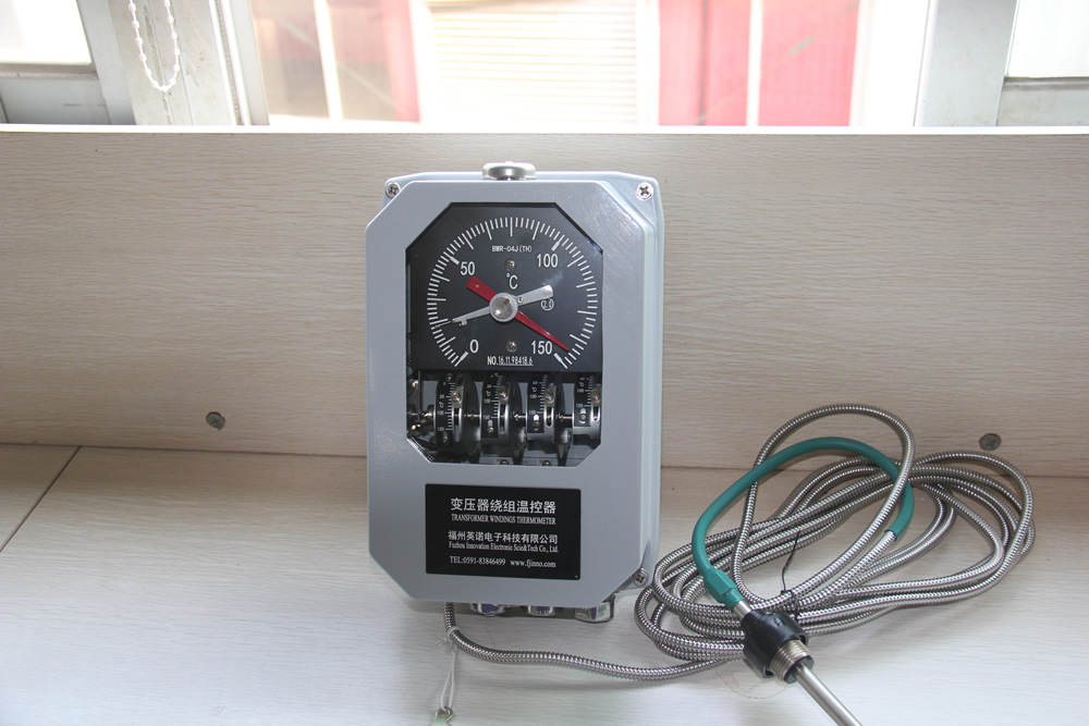
Transformer winding thermometer is a special instrument used to measure the temperature of oil-immersed power transformer winding, which indirectly reflects the winding hot spot temperature through the "thermal simulation" method, is one of the core components of the transformer operation status monitoring.
I. Structure and composition
-
Meter body: pointer type or digital display type, dial usually has white real-time pointer, red maximum value pointer, and four-color (red, blue, green, yellow) contact indicator block.
-
Temperature package: The metal temperature sensing package is placed in the oil on top of the transformer at a depth of ≈ 150 mm and filled with temperature sensing medium.
-
Capillary/Spring Hose: Connects the temperature package to the gauge head and transmits the medium expansion displacement.
-
Thermal simulation device:
- Converter: Converts high voltage side casing CT secondary current (0-5 A or 0-1 A) to 0-1 A (typical) heating current at the manufacturer's ratio.
- Heating element: This current flows through a heating wire placed inside the heating pack and generates an additional temperature rise Δt proportional to the load. -
Auxiliary components:
- Microswitch: Provides alarm/trip/start/stop cooler contacts for groups K1~K6.
- PT100 platinum resistance: Outputs 4-20 mA or RS-485 (Modbus) remote signals for background monitoring.
II. Principle of operation
-
At no load or low load: The temperature pack is only affected by the top oil temperature tₒ, which is indicated by the pointer as tₒ.
-
After carrying a load:
t_winding = tₒ + k-I²
where k is the thermal simulation coefficient, which is determined by the converter ratio in conjunction with the resistance of the heating wire. The additional heat generated by the heating current on the heating wire simulates the temperature rise of the winding copper, thus making the meter value close to the hot spot temperature of the winding. -
Output:
- Mechanical pointers are displayed in situ;
- The microswitch closes/disconnects at the set value to actuate the cooler or protection circuit;
- PT100 or 4-20 mA signal to DCS/backend for remote monitoring.
III. Installation and maintenance points
-
Installation: The temperature package is inserted vertically into the special oil hole, and the bending radius of the capillary tube is ≥40 cm, avoiding twisting and sharp bends.
-
Electrical: All wiring must be done in a power-off state, with the junction box well sealed and reliably grounded.
-
Calibration: According to JJF(Jin)XX-2024 and other specifications, the display value and contact action error calibration is carried out at 10 ℃, 20 ℃, 38 ℃ temperature rise points, and the display value error of the remote transmission ≤ 1/2 of the absolute value of the maximum permissible error.
-
Daily inspection: Check whether the pointer is stuck, the maximum value pointer reset, and the contact action is reliable, to prevent analog failure due to capillary leakage or broken heating wire.
IV. Comparison with traditional temperature measurement
-
Directly buried sensors: high accuracy, but need to be pre-buried fiber optic or RTD when the transformer is manufactured, and difficult to transform later.
-
Pure oil thermometer: reflects only the top oil temperature, not the additional temperature rise of the winding caused by the load current.
-
Winding thermometers: taking into account the economy and engineering implementability, widely used in operating transformers.
By means of the above thermal simulation technique, the winding thermometer realizes the effective monitoring of the winding hot spot temperature without contacting the winding body, providing key data for the transformer's "load guideline" operation and life assessment.