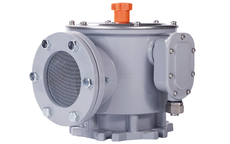
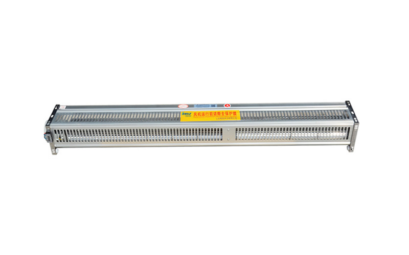
YSF series Φ80mm, Φ130mm caliberpressure relief valveIt is mainly applicable to the pressure release when the oil tank of large oil-immersed power transformers, power capacitors, reactors and other equipments are overpressurized.
When the oil-immersed power transformer tank internal pressure rises sharply due to accidents, this pressure, if not released in time, will cause the tank deformation or even burst. Pressure relief valve can be in the tank pressure rises to its opening pressure value, quickly open, so that the pressure inside the tank is quickly reduced. When the pressure drops to the closing pressure value of the pressure relief valve, the pressure relief valve closes reliably, so that the positive pressure is always maintained in the fuel tank, effectively preventing external air, water and other impurities from entering the fuel tank. The pressure relief valve with directional oil injection device (hereinafter referred to as directional oil injection pressure relief valve) can spray out the released transformer oil directionally, and through the oil conduit into the oil collection tank, preventing the oil from splashing to meet the requirements of fire prevention and environmental protection.
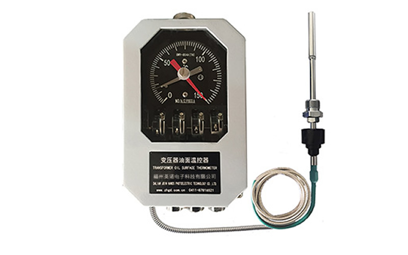
Φ80mm, Φ130mm caliber pressure relief valve, in addition to the conventional electrical alarm signal, can also be added to the computer with the electrical alarm signal function, you can realize the dual electrical signal output, and each independent of each lead, users can order products according to the needs of the selection.
model number
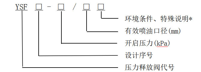
instructions: D-indicates with directional oil injection, K-indicates with electrical signaling, SK (or KK)-indicates with dual electrical signaling, J-indicates with mechanical signaling, TH-indicates for use in humid tropics, and B-indicates with lockout device. Note: YSF10,YSF12,YSF14 are directional release valves. z
For example: YSF9-55/130DSKJTHB is the pressure relief valve with Φ130mm injection caliber, 55kPa opening pressure, directional injection, mechanical and dual-channel electrical alarm signals, and locking device for use in wet tropics based on the second improvement of the ninth design.
Specifications and performance parameters
Units:mm -Table 1-
| Effective caliber (mm) | Φ80 | Φ130 | ||||||||||
| Opening pressure (KPa) | 35 | 55 | 85 | 55 | 70 | 85 | 100 | 138 | ||||
| Limit deviation (KPa) | ±5 | ±10 | ||||||||||
| Closing pressure (KPa) | 19 | 29.5 | 45.5 | 29.5 | 37.5 | 45.5 | 54 | 74 | ||||
| Sealing pressure (KPa) | 21 | 33 | 51 | 33 | 42 | 51 | 60 | 82.8 | ||||
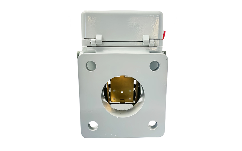
Structure and mounting dimensions
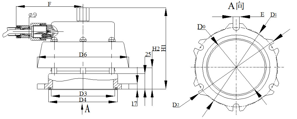
Figure 3
-Table 4-
| norm | D0 | D1 | D2 | D3 | D4 | D6 | E | F | H1 | H2 |
| YSF9-80K | 122 | 170 | 200 | 132 | 151 | 200 | 14 | 140 | 170 | 45 |
| YSF9-130K | 180 | 235 | 260 | 188 | 208 | 260 | 18 | 165 | 190 | 55 |
Features:
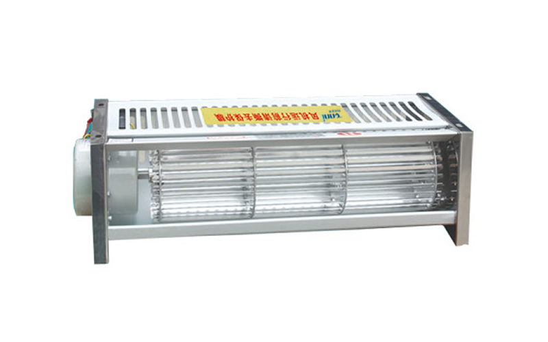
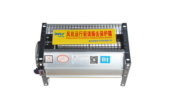
Ф80mm, Ф130mm caliber pressure relief valve features: electrical switch built-in, high safety and reliability, to prevent accidental bump damage and false alarms due to rain and fog, stainless steel shell, three-proof performance, junction box built-in terminals, wiring is convenient and safe, junction box can be connected to the outside of the wire sheath.
Selection of pressure relief valves
Caliber Selection:
The selection of the caliber of the pressure relief valve is divided according to the size of the transformer capacity, and is selected with reference to -Table 5-
| Injector caliber(mm) | Φ130 | Φ80 |
| Capacity (kVA) | >31500 | ≤31500 |
Quantity Selection:
For large transformers need to install more than two Ф130mm caliber pressure relief valve, you can refer to the following formula:
Total oil volume (t(a) /23=Ф130mmNumber of pressure relief valves for caliber (round up to the nearest whole number)
Turn on the pressure selection:
Pressure relief valve opening pressure selection should give full consideration to the sealing pressure, pressure relief valve sealing pressure should be greater than the maximum allowable transformer operating pressure of 5 ~ 10 kPa, this is the pressure relief valve opening pressure selection of the first condition.
Installation and use
The sealing pressure can be found from Table 1, according to which the sealing pressure can be obtained from theTable 6Find out where the pressure relief valve is mounted on the tank. The pressure relief valve should be mounted on the tank cover, or tilted (0 to 90°) if necessary.
-Table 6-
| Opening pressure (kPa) | 35 | 55 | 70 | 85 | 100 |
| Sealing pressure (kPa) | 21 | 33 | 42 | 51 | 60 |
| H (m) | 1.41 | 2.63 | 3.57 | 4.51 | 5.4 |
H-Maximum distance from the highest oil level of the tank to the installation position of the pressure relief valve (additional safety margin pressure 7kPa)
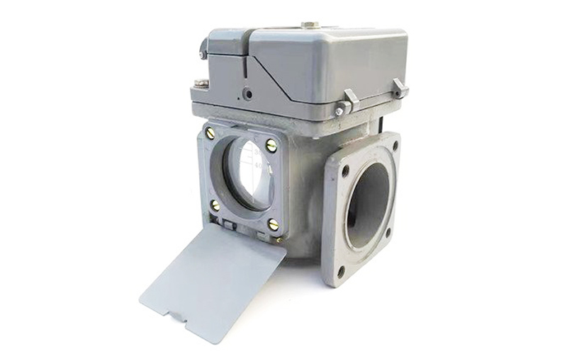
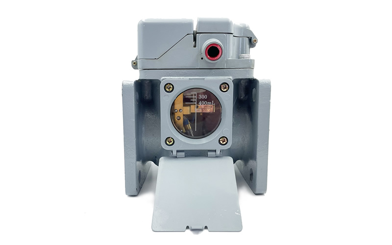
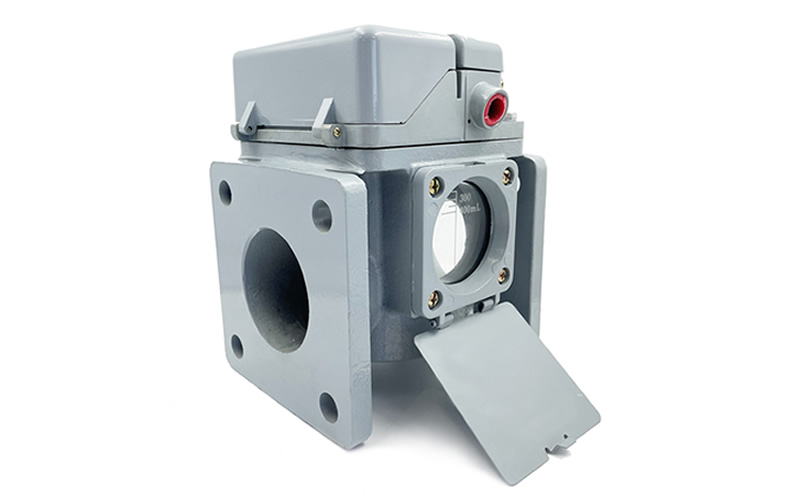
Installation should be equipped with the pressure relief valve with the flange (the user to provide), the shape of the seeFigures 1, 2, 3For dimensions seeTables 2, 3 and 4The
Note: Our company can provide two specifications of the bottom rubber ring, which can realize the gapless coupling and the gap coupling, if there is no special indication, the products are always configured with the bottom rubber ring for the gap coupling when they are shipped from the factory.
The external flange of the directional oil injection outlet can be welded with a conduit to direct the oil into the sump.Figure 2The
Pressure relief valve locking device locking state, this locking device can withstand the tank 0.06MPa pressure, that is, the transformer tank oil pressure test pressure relief valve can withstand the inaction pressure for: open pressure + 0.06MPa. (Such as: Model: YSF9-55/130DSKJTHB pressure relief valve, in the transformer tank oil pressure test, the pressure Release valve can withstand: 55 + 0.06 × 10³(KPa = 115 KPa without action.)
The pressure relief valve must have the latching device removed before commissioning to ensure a reliable alarm.
The mechanical and electrical signals of the pressure relief valve should be manually reset after the operating pressure relief valve has been actuated.
The product has been rectified and qualified before leaving the factory, and the user cannot disassemble it at will.
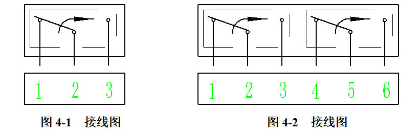
Pressure relief valve signal switch connection and basic parameters (seeFigure 4,Table 5This product can be equipped with two sets of the same independent alarm signal switches (two sides of the wire when each side is connected as follows).Figure 4-1; When the same side of the outlet line is connected as followsFigure 4-2), one of which can be used in a computerized management system, and a wiring schematic on the product nameplate.
-Table 5-
| Voltage type | Voltage (V) | Resistive load (A) | Inductive load (A) |
| AC | 250/125 | 3/5 | 3 (COSФ=0.4) |
| DC | 220 | 1.5 | 0.25 (T=7ms) |