


What are partial discharges in cables and their hazards?
partial dischargeIt is a discharge phenomenon of impulse nature in electric equipment. Whencable gland,cable bodyet al.partial dischargeWhen it does, it produces a series of detectable physical and chemical changes within the device and in the surrounding space:
- optical signal: Faint optical radiation from electrical discharges
- acoustic signal::ultrasonic vibrationharmonic emission
- Electrical signals: Pulse current andelectromagnetic radiation
- mechanical vibration: Structural vibrations due to discharge shocks
- chemical change::insulating materialDecomposition and gas products
These concomitant phenomena aremonitorselectricinsulation conditionProvides an importantdetected signalBasis.
Why are cable joints prone to partial discharges?
cable glandand other critical areas are often the result ofpartial discharge phenomenon::
- loose or defective contact (elec.): Poorly crimped joints, creating localized high electric fields
- Aging of the medium::insulating materialPerformance degradation due to long term operation
- water intrusion: Poor sealing leads toisolateaffected by damp and cold
- construction defect: Improperly crafted and left behindinsulation hazard
- environmental factor: Temperature and humidity changes accelerate aging
suchInsulation defectsNot only will it accelerateInsulation agingIt may also trigger(electric) cablebreakdown, short circuit and other seriouspower accidentThe
Why do I need cable localized on-line monitoring?
This is accomplished through a review of thecable localized amplifier signal(used form a nominal expression)Detection and analysisYou can:
- timely detection: Detection at an early stageinsulation hazard
- judgement: Identificationlocalization typeand severity
- accident prevention: Prevent further expansion of potential accidents
- extend life: Guided maintenance, extended(electric) cableservice life
- reduce costs: Avoiding economic losses from sudden power outages
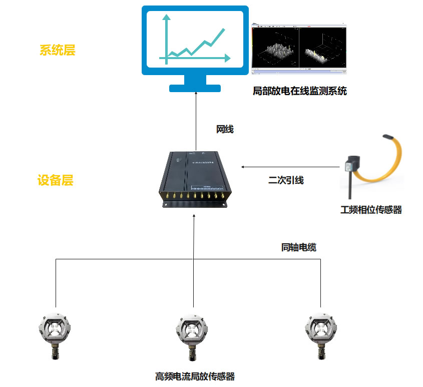
Cable partial discharge online monitoring system为power systemIt provides an important technical guarantee for the safe and reliable operation of the
Local Discharge Sensor
High-frequency pulsed-current local-discharge insulation monitoring technology is an online monitoring technology based on high-frequency pulsed-current local-discharge sensors. The technology is realized by using the(electric) cablegroundingHigh-frequency pulse current local discharge sensors are installed at the site to monitor the local discharge signals in real time. Different types of partial discharges have different electrical breakdown processes, resulting in pulse currents of different amplitudes and steepness, and therefore electromagnetic transients and electromagnetic waves of different frequency components. The high-frequency coil detects the size of the signal for data sampling, and uses advanced signal processing algorithms to analyze and identify the signal, thus realizing an accurate assessment of the insulation state.
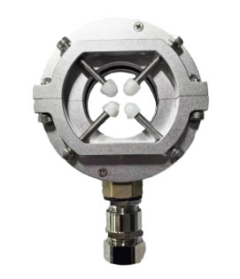
High Frequency Current Local Discharge Sensor
Products
The product is a high-frequency pulse current local discharge sensor, need to be used with the local discharge acquisition device, real-time monitoring of the state of electromagnetic wave radiation around the sensor cable, monitoring the occurrence of partial discharge generated by the high-frequency current signals, the signals are transmitted to the local discharge acquisition device, and finally, the upper computer or the backstage system receives the data to form a map via Ethernet.
Product Features
- Designed with a variety of anti-interference measures, it can operate stably in the power system.
- Easy and solid installation, not easy to fall off.
- High monitoring accuracy allows accurate monitoring of the type of discharge.
Product Features
| monitoring function | Real-time monitoring of the electromagnetic wave radiation status around the distribution sensor, monitoring the high-frequency current signal generated when partial discharge occurs in the cable grounding. |
| output function | and transmit the collected high-frequency current signals to the local-amplifier acquisition unit. |
Technical indicators
| Fuselage parameters | Monitoring bands | 100kHz ~ 50MHz |
| Sensor sensitivity | 5pc | |
| impedance matching | 50Ω | |
| Minimum monitoring | <=-75dBm | |
| dynamic range | -80dBm~-20dBm | |
| caliber | >=60mm | |
| coaxial cable | Conventional 5 meters, optional 5, 10m (signal weakens according to wire length) | |
| working environment | temp | -40℃~85℃ |
| humidity level | ≤95%RH |
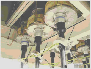
Installation
- Installation location is at the three-phase cable or at the grounding cable.
- After determining the position, first twist the high-frequency current sensor, if the size is suitable, you can directly snap the sensor on, tighten the fastening screws, pay attention to the direction of the RF wire facing down, if the size is small you can choose to use a tie or other tools to fix it.
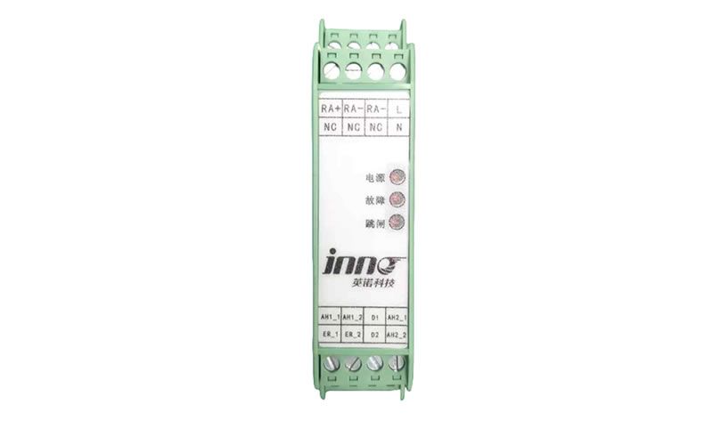
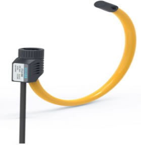
Industrial Phase Sensors
Products
Industrial frequency phase sensors are non-contact sensors that can directly measure voltage and current phase differences in power systems.
It consists of three main parts: the magnetic core, the coil and the signal processing circuit. When the current in the system passes through the coil, it will generate a magnetic field in the core, and this magnetic field will change with the current. At the same time, the coil in the sensor senses the change in this magnetic field, which generates a voltage signal. The magnitude and phase of this voltage signal is related to the current in the system.
Product Features
- Pure copper coils are tightly arranged, thickened copper wire for low resistance and high stability.
- Flame retardant housing design, non-flammable when exposed to open flame, high insulation protection
- Inner core silicon steel iron core, strong magnetic conductivity, durable and non-heating, strong load-bearing capacity
- Optimized design, easy to install, easy to install when modifying wiring
Product Features
| Phase Sequence Detection | By measuring the phase difference between current and voltage, it determines whether the phase sequence of the system is correct. |
| Power quality analysis | The specific causes of power quality problems are analyzed by measuring information such as phase differences and harmonics of voltage and current. |
| Electricity metering | Power quality is monitored by measuring the phase difference between current and voltage and calculating the power consumption. |
| Protection control | It can be used as the input signal of various protection and control devices in the power system to realize the protection and control of the power system. |
Technical indicators
| model number | CTLS1 |
| accuracy | 5% |
| linearity | 0.50% |
| Inner Bore Diameter | 150mm |
| Response bandwidth | 1Hz to 1MHz |
| IP Protection Rating | IP65 |
| compressive strength | 2KVAC / min |
| electrical insulation resistance | DC500V/ 100MΩ |
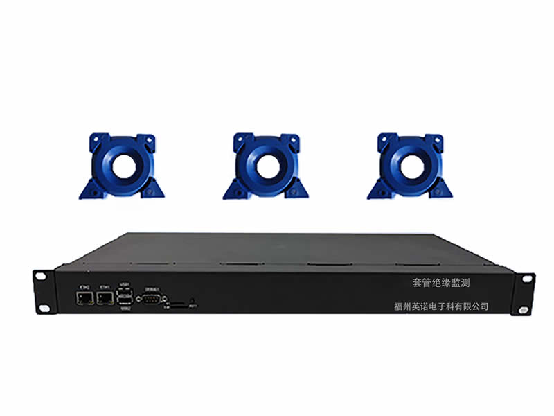
Mainframe of cable localization in line monitoring system
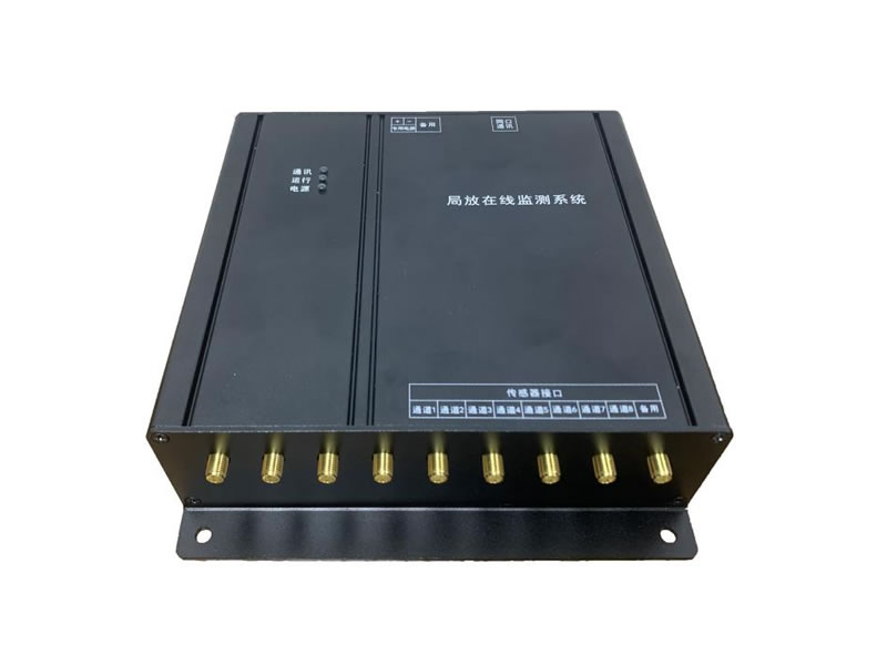
Products
Local in line monitoring system at any time can monitor the high-frequency current local discharge sensor back to the local discharge signal, signal conditioning, buffer isolation, after filtering, signal amplification, complete high-speed acquisition, complete the measurement of a number of industrial frequency cycle time period, the sensor monitored electromagnetic wave carried out the maximum discharge amplitude, the average amount of discharge, the number of discharges and other effective data for measurement and calculation.
Product Features
| receive function | Responsible for receiving high-frequency current signals from high-frequency current local discharge sensors. |
| processing function | The collected signals are conditioned, buffered and isolated, filtered and signal amplified to complete high-speed acquisition and measurement of multiple IF cycle time periods. |
| Computational Measurement | Effective data such as maximum discharge amplitude, average discharge, and number of discharges were measured and calculated for the electromagnetic waves detected by the sensor. |
| data output | With RJ45 network transmission interface, it can meet the demand for centralized collection, analysis and processing of partial discharge monitoring data as well as uploading to the background. |
Technical indicators
| power supply | DC12V/AC90~240V, 50~60HZ |
| power (output) | ≤5W |
| detection band | 100kHz ~ 50MHz |
| Minimum monitoring | <=-75dBm |
| dynamic range | -80dBm~-20dBm |
| Number of channels | 3-8 channels |
| Channel Consistency | <0.5dBm |
| Installation | Wall-mounted or rack-mounted |
| overvoltage protection | Sensor built-in |
| input channel | Synchronized detection |
| synchronization signal | Optional external and internal simultaneous |
| communication interface | RJ45 network port, RS485 communication port, spare port |
| output result | Discharge size, discharge phase, discharge type, number of discharges, etc. |
| Overall dimensions | 204mm x 177.4mm x 53mm |
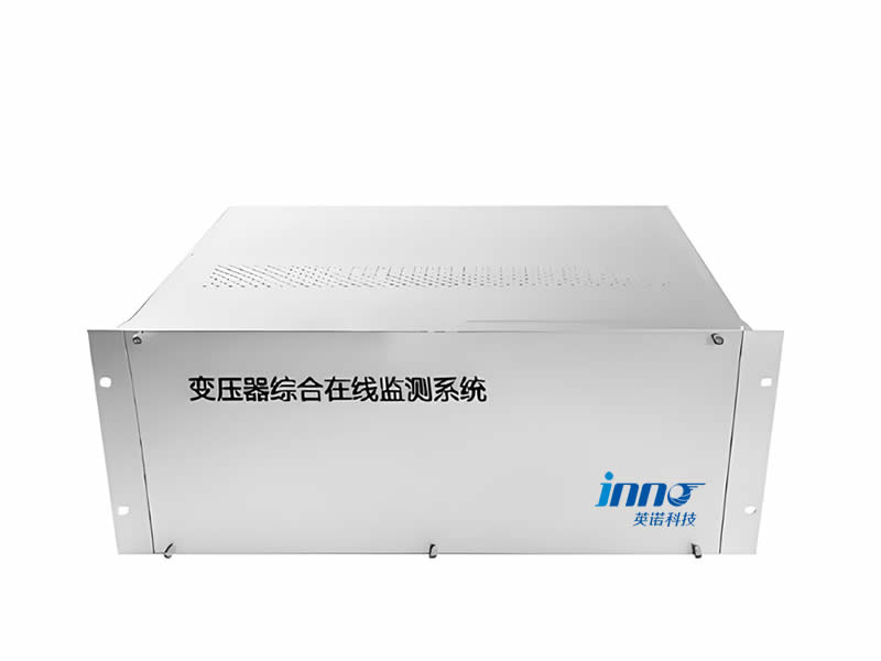
Partial Discharge Online Monitoring System
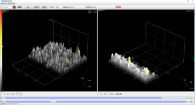
System Introduction
The system is installed in the background computer of the main control room, which can monitor the partial discharge of the associated equipment in the operating state. The system software function is designed to be reasonably laid out and easy to operate, and the data is presented through graphical analysis, which is more intuitive.
system function
| Real-time monitoring | Can monitor, store and correlate equipment operating status partial discharge high frequency current local discharge data; 3D spectrogram. |
| search function | Can query historical data curve, with statistical analysis, trend analysis function. |
| parameterization | With functions such as device parameter configuration and threshold setting, the main parameters can be programmed and set. |
| Type of monitoring | The monitored data includes data such as mean and peak values of amplitude, alarm levels, and plots. |