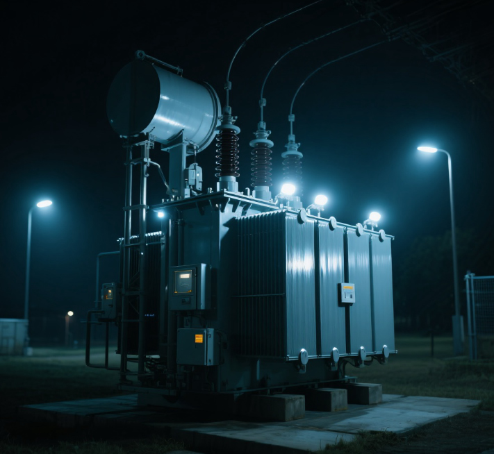
Main transformer oil level remote transmission Transformer oil level meter function technical requirements
Date: August 15, 2025 10:41:13
Main transformer oil level remote transmission is through the sensor collection transformer oil level signal, and will be transmitted to the remote monitoring system (such as control room SCADA, backstage monitoring), to realize the oil level remote real-time monitoring and abnormal alarm technical solutions, the core role is to avoid the hysteresis of manual on-site inspection, to ensure the safe operation of the transformer.

The following is a general introduction and does not represent the parameters of our products. Contact us for details!
I. Core components
-
Oil level sensor (field acquisition unit)
Installed on the transformer tank or oil storage cabinet, it is the core of signal acquisition, and the mainstream types are as follows:- Float Sensors: Using the float with the oil level rise and fall to drive the mechanical structure (such as magnets), triggering the reed switch or Hall element output switching (high and low oil level alarm) or analog (4-20mA continuous oil level).
- Capacitive SensorsThrough the difference of dielectric constant of oil/gas medium, the change of oil level is converted into change of capacitance value, which is converted into standard electric signal by circuit, adapting to high temperature and strong electromagnetic environment, with high precision.
- Ultrasonic sensors: Non-contact measurement that calculates the oil level height by transmitting ultrasonic waves and receiving reflected waves from the liquid level, suitable for scenarios where it is not advisable to install a contact sensor.
-
signal transmission unit
- Transmission medium: mostly usedShielded cables(anti-electromagnetic interference), or converted to digital signals (RS485, Ethernet) for transmission via measurement and control devices (e.g. intelligent terminals) in the transformer body.
- Signal Type:
- Analog: 4-20mA (mainstream, strong anti-interference ability, corresponding to the oil level 0-100%);
- Switching quantity: 2-3 groups (corresponding to low oil level, normal oil level, high oil level/overflow alarm);
- Digital: Transmission via Modbus, IEC 61850 and other protocols, supporting remote configuration and calibration.
-
Remote monitoring unit
Receive the transmitted signal and realize it:- Real-time display: Display the oil level as a numerical value, bar graph or analog dial in the monitoring interface;
- Alarm linkage: when the oil level exceeds the limit (low oil level oil shortage, high oil level oil overflow), it triggers acoustic and visual alarms, logging, and even linkage of transformer protection logic (e.g. low oil level blocking voltage regulation);
- Historical traceability: Stores oil level data and supports trend analysis (e.g., determining slow oil leakage).
II. Key technical requirements
-
environmental adaptation
Sensors need to withstand the high temperature of transformer operation (usually - 30 ℃ ~ 100 ℃), strong electromagnetic interference (transformer leakage), and with explosion-proof, oil corrosion resistance (stainless steel, fluorine rubber and other materials). -
Measurement accuracy
The error is usually required to be ≤±1% (full scale) to avoid false alarms or missed alarms (e.g., minor leaks that cannot be recognized) due to lack of accuracy. -
Redundancy and Reliability
- Critical transformers can be designed with "dual sensor" redundancy to avoid a single point of failure;
- Signal cables need to be laid independently, away from high-voltage cables to reduce signal distortion caused by electromagnetic interference.
-
temperature compensation
Transformer oil volume changes with temperature can lead to "false oil level" (such as oil temperature rise oil level appears to rise), part of the sensor built-in temperature compensation function, through the oil temperature signal to correct the oil level measurement value, to ensure that the data is true.
III. Common problems and treatment
| Faq | Possible causes | Recommendations for handling |
|---|---|---|
| No change in oil level signal | Sensor jamming (float type), cable breakage | Checking sensor mechanics, measuring cable on/off |
| Large deviation of oil level display | Failure to compensate for temperature, sensor calibration failure | Enable temperature compensation, recalibrate sensors |
| false alarm | Electromagnetic interference, improperly set sensor thresholds | Check shield grounding, adjust alarm thresholds |
IV. Application implications
- safety protectionReal-time monitoring of oil shortages (leading to insulation/heat dissipation failures), oil spills (leading to fire risks) and timely triggering of alarms;
- Operations Optimization: Reduce the frequency of manual inspections and anticipate abnormal oil level trends (e.g., chronic leakage) through historical data;
- Unattended Adaptation: Provide key state data support for the unattended mode of substation, in line with the development needs of smart grid.
How to choose the right oil level telemetry solution for your main transformer?
Selection of the main transformer oil level telemetry program needs to be combined with aTransformer parameters, site environment, functional requirements, operation and maintenance costsThe four core dimensions follow the principle of "prioritizing adaptability, reliability, and balancing economy", and the specific steps and key considerations are as follows:
First, first clear transformer's own core parameters (basic premise)
The structure and operating characteristics of the transformer directly determine the suitability of the solution, and priority should be given to confirming the following parameters:
-
Transformer capacity and voltage level
- Large-capacity (≥110kV) or important station transformers (e.g. main transformers in hub substations): higher reliability is required and recommended.Dual sensor redundancy design(e.g., primary and backup capacitive sensors) to avoid a single point of failure that would render monitoring ineffective;
- Small and medium capacity (35kV and below) or distribution transformers: the solution can be simplified by choosing a single sensor (e.g. float type) to reduce costs.
-
Type of oil conservator
The structure of the oil conservator determines how the sensor is mounted and needs to be precisely matched:Type of oil conservator Structural characteristics Recommended Sensor Types caveat Open Oil Storage Cabinet Direct contact with the atmosphere makes it susceptible to contaminants/vapor. Float type (with sealing structure), capacitor type Sensors need to be checked regularly for fouling resistance Capsule / Diaphragm Oil Storage Cabinets Oil is isolated from the atmosphere and has an internal elastic capsule Capacitive (non-contact), ultrasonic type Avoid direct friction between sensor and capsule to prevent breakage Corrugated Oil Storage Cabinet Metal bellows retracts to regulate oil level Capacitive (Side Mount), Magnetostrictive The sensor has to be adapted to the expansion and contraction stroke of the bellows.
II. Matching site environmental conditions (key constraints)
The field environment is a "hard threshold" for sensor selection, and the following factors need to be evaluated in focus:
-
temperature range
- Cold areas (such as northeast, northwest): choose low temperature resistant sensors (operating temperature ≥ -40 ℃), to avoid float type sensors due to low temperature icing stuck;
- High-temperature environment (e.g. outdoor in the south, closed plant): choose capacitive or ultrasonic type with temperature resistance ≥120℃ to avoid high-temperature aging of plastic parts.
-
electromagnetic interference (EMI) strength
Transformer body magnetic leakage and electromagnetic radiation from high voltage cables can affect signal transmission and need to be:- Sensor: Preferredcapacitive(high resistance to electromagnetic interference), avoid selecting the float type with Hall elements (susceptible to magnetic field interference);
- Transmission cable: must beShielded Twisted Pair(such as RVVP type), and independent laying (away from 10kV and above high-voltage cables), both ends of a good grounding (grounding resistance ≤ 4Ω).
-
Fouling and Explosion Protection Requirements
- Outdoor dirty areas (e.g. industrial areas, coasts): the sensor housing needs to be selected.IP65 and above(dust-proof, rain-proof), material priority stainless steel (corrosion-resistant);
- Explosion-proof environments (e.g. chemical substations): must useEx d IIB T4 and above explosion-proof gradeof the sensor to avoid the danger caused by electric sparks.
III. Defining functional and operation and maintenance needs (core objectives)
Based on the functional orientation of the monitoring system, select a technical configuration that meets the requirements:
-
Measurement accuracy requirements
- Precision monitoring (e.g. main transformer condition maintenance): selectCapacitive or magnetostrictive(Error ≤ ±0.5% FS), supports continuous oil level monitoring for trend analysis;
- Base alarm (high and low oil level only): selectablefloat(Error ≤ ±2% FS), low cost, to meet the demand for switching alarms can be.
-
Signal Transmission and Compatibility
It needs to be matched with remote monitoring system (e.g. SCADA, backend) to avoid "signal incompatibility" problem:- Conventional substations (analog-based): Selection of4-20mA analog outputThe sensors are connected directly to the PLC or RTU;
- Intelligent substations (digitization-based): select supportIEC 61850/MODBUS protocolsThe digital sensors are connected to the intelligent terminal via Ethernet or RS485 to realize data intercommunication.
-
Alarm and Linkage Requirements
- Basic requirements: Support at least 2 sets of switching outputs for "Low oil level alarm" (oil shortage) and "High oil level alarm" (oil overflow);
- Advanced requirements: to be supportedAlarm for sudden change of oil level(e.g. rapid drop of oil level in a short period of time is judged as oil leakage), and linkage protection logic (e.g. low oil level blocking on-load voltage regulation).
-
Temperature compensation function
Transformer oil due to temperature changes will produce "false oil level" (oil temperature rise → oil volume expansion → oil level false high), need to confirm whether the sensor withBuilt-in temperature compensation::- Outdoor or scenarios with large temperature differences (day/night temperature difference ≥ 20°C): Sensors with temperature compensation (e.g. capacitive + PT100 temperature acquisition) must be selected to ensure true oil level data;
- Indoor constant temperature environment: can be simplified without forced temperature compensation.
IV. Balancing reliability and cost (economic fitness)
Optimize full life-cycle costs to avoid "over-designing" or "under-pricing and under-quality" while meeting demand:
-
Initial investment vs O&M costs
Type of program Initial cost Difficulty of operation and maintenance Applicable Scenarios Float type (switching) lower (one's head) Medium (requires periodic inspection of mechanical components) Small to medium capacity, basic alerting requirements Capacitive (analog) center Low (no mechanical wear) Large capacity, precision monitoring, strong electromagnetic environment Ultrasonic type (digital) your (honorific) Low (non-contact measurement) Special structure oil conservator (e.g. corrugated), explosion-proof environment -
Redundancy design trade-offs
- Non-critical substations (e.g. distribution terminals): single sensor + backup cable, no redundancy required;
- Key substations (e.g., hub stations, power plant main transformers): must be dual sensor (independent power supply, independent transmission), and tap into different measurement and control devices to ensure "one backup, one use".
V. Verification of compliance and compatibility (final guarantees)
- Standards Compliance: Choose products that meet industry standards, such as "DL/T 1502-2016 Technical Conditions for Transformer Oil Level Monitoring Devices", to avoid non-standard products that cannot be connected to the power monitoring system;
- interface compatibilityConfirm that the sensor's power supply (usually DC24V) and signal interface (e.g., 4-20mA terminal, RS485 interface) are compatible with the on-site measurement and control device to avoid rework due to "interface mismatch";
- Manufacturers' ServicesPriority is given to manufacturers that have a track record in the power industry, provide on-site commissioning (e.g. oil level calibration) and after-sales protection (e.g. 1-year warranty), so as to reduce the risk of operation and maintenance at a later stage.
Summary: Selection Decision Process
- Confirm transformer parameters (capacity, reservoir type) → 2. Evaluate site environment (temperature, electromagnetic, explosion-proof) → 3. Define functional requirements (accuracy, transmission, alarms) → 4. Balance cost and reliability → 5. Verify compliance and compatibility.
Through the above steps, it can ensure that the selected solution "adapts to the site, meets the needs, is stable and reliable", and avoids oil level monitoring distortion or equipment failure due to improper selection.
![]()


