



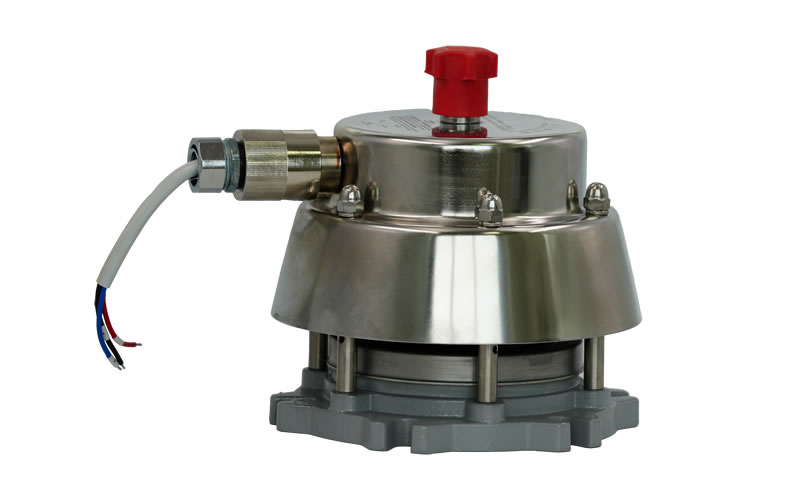
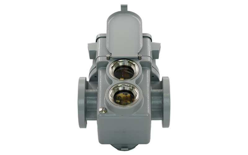
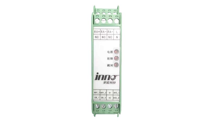
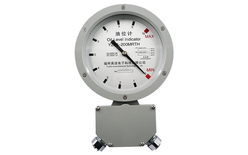


Passive wireless temperature measurement device is a temperature measurement product used in medium and low voltage power systems (0.4kV-35kV) and applications with high requirements for temperature. It is a modernized high-tech product integrating online temperature measurement and data acquisition. Its technical indicators can reach the requirements of the national standard, the temperature measurement device can be collected online contact temperature (contact number 1 to 12). The device can provide RS485 communication interface to transmit data to the station temperature measurement management device or the main station of the temperature measurement system, supports MODBUS-RTU communication protocol, communication baud rate can be set. A variety of anti-interference measures have been adopted in the design to enable stable operation in the power system. Shell protection class IP20, sensor protection class IP65.
Key Features
1) Multiple wireless measurement of temperature real-time data display, can receive 1 to 12-way contact temperature data.
2) With equipment parameter configuration function, the main parameters can be programmed and set.
3) With display interface and RS485 communication interface, conventional temperature measurement terminal without display, optional temperature display instrument.
4) Data communication transmission function, all data can be transmitted to the upper level temperature measurement device or temperature measurement system master station through the data communication interface.
Technical Parameter
1) Working power supply: AC/DC 220V.
2) Temperature measurement channel: single system supports a maximum of four channels of 12 temperature measurement points, the standard configuration of 6 temperature measurement points.
3) Working environment temperature: -20℃~+70℃.
4) Working environment humidity: ≤95%RH.
5) Communication interface: multi-channel RS485 interface (including debugging, display, communication applications), using MODBUS-RTU communication protocol, one start bit, eight data bits, no parity, one stop bit. Baud rate can be set to 1200bps, 2400bps, 4800bps, 9600bps.
6) RS485 communication interface can be realized with the end of the temperature measurement management device to transmit data, the longest distance <1000 meters.
7) Contact temperature measurement range: -25℃~125℃.
8) Temperature accuracy: ≤ ± (standard reading × 1% + 1) ℃.
9) Temperature display resolution: 0.1℃.
Mounting Dimensions and Wiring
make up
1) Temperature collector realizes wireless reception, preservation and forwarding of the temperature of the contacts in the cabinet;
2) Temperature sensors, typical configuration of 6 channels in each switchgear.
3) Collector transceiver antenna is standard.
Temperature Collector Picture and Structure Dimension


Temperature collector external dimensions: 162 × 88 × 38 (unit: mm)
Installation
1) Two-point screw fixing and 35mm rail mounting are available.
(2) The temperature collector is installed in the switch cabinet, which can be fixed and installed with Φ3 screws or ties at the position of 144mm hole spacing, or you can choose the standard 35mm rail mounting, and the collector transceiver antenna is arranged in the inner wall of the switch cabinet near the installation position of the temperature sensor, and the antenna lead is introduced into the instrumentation room of the switch cabinet through the wire slot, avoiding the touching and proximity to the strong power lines, and realizing the wireless signal transmission and reception of passive wireless temperature sensors by the collector through the antenna. The collector can transmit and receive wireless signals from the passive wireless temperature sensor through the antenna.
(3) According to the site installation requirements and different cabinet types, respectively, choose a single-channel temperature acquisition or dual-channel temperature acquisition, each additional channel needs to be configured with a set of antennas, it is recommended that the use of dual-channel can be applied to the majority of types of switchgear cabinet installation application requirements.
Note: When installing the temperature collector, please install the supporting antenna at the same time, reserve and install the power supply line and independent switch, arrange the communication line used for RS485 communication data collection, and then install and fix the temperature collector in the appropriate position inside the switch cabinet to complete the installation.
temperature sensor
Temperature sensors mainly use tuning fork type, snap type and spring type several kinds of temperature sensors, installed in the need to measure the temperature of the electrical contact position, when the measured temperature is greater than the set tripping and alarm value, can be combined with external sound, light alarm to achieve the limit of the alarm of the integrated alarm prompts.
Outline drawing and dimensions:

tuning fork |

snap |

nut-based |
Features and Parameters
1. Temperature-resistant (-40℃~+250℃) flame retardant material, waterproof, no deformation or dripping under high temperature.
2. No external power supply, no internal battery, wireless sensing signal temperature measurement, passive wireless transmission.
3. Small size, easy to install, adapt to a variety of scenes.
4. Up to 99% linearity, the package meets the high protection level of IP65.
5. Minimalist structure, high reliability, long life (>10 years).
Temperature Sensor Installation
Temperature sensors, respectively, installed in the important temperature measurement contact, different installation locations can be selected from different packages of temperature sensors. Installation order is generally in accordance with the number from small to large respectively corresponds to the circuit breaker contacts (busbar or knife gate) on phase A, phase B, phase C, phase A, phase B, phase C, phase A, phase B, phase C, respectively.
Tuning Fork Temperature Sensor Installation
① The cabinet should be de-energized before installation.
② Loosen the screws on the electrical connection part and insert the tuning fork temperature sensor U-slot under the screws.
③ Adjust the sensor position so that the bottom of the sensor is in better contact with the temperature measurement position, and re-tighten the screws according to the torque requirements.
Snap-on Temperature Sensor Installation
① It is mainly installed on the contact fingers of the movable contacts of the circuit breakers of the transfer switchgear, and the trolley circuit breakers need to be removed before installation.
② First, attach the snap-on temperature sensor to the upper surface of one of the contact fingers of the movable contact, thread the mounting bracket upward from underneath the contact finger and connect the supporting screw and nut with the sensor to the connection, tighten the bracket so that the sensor is close to the upper surface of the contact finger, and indent the screw to complete the installation.
Nut Temperature Sensor Installation
① Select the appropriate size of the nut, which is mainly installed in the cable connector of the ring network cabinet, and needs to be de-energized before installation.
② Mounting the sensor: Place the sensor in contact with the object to be measured and secure it with nuts and washers. Make sure that the contact between the sensor and the object to be measured is tight to ensure accurate temperature measurement.
③ Screw in the nutted temperature sensor and make sure that the cable is firmly connected to avoid signal interference or measurement errors. Connect the cable: Connect the cable of the sensor to the corresponding measuring instrument or data acquisition system. Complete the installation.
Other Installation Precautions
1 Installation in the circuit breaker moving contact position, need to shake the trolley installation; if installed in the inlet and outlet busbar or cable lap point position, the cabinet busbar must be de-energized to allow installation and operation;
2 The bottom of the temperature sensor for the temperature-sensitive parts, need to be close to the surface of the measured position, the surface is not flat can be used to fill the thermal conductive silicone grease, thermal conductive silicone grease should be flat, uniform, is more conducive to temperature conduction;

Collector Transceiver Antenna
In order to facilitate the use of high-voltage environment, the collector transceiver antenna should be as small as possible under the premise of ensuring the gain, so as not to affect the safety distance of high-voltage equipment. Our specially designed collector antenna for power equipment, the thickness is only 21mm, can be fixed in the switchgear cabinet by screws.

Temperature display meter (optional)
| Product Pictures |
|
| name (of a thing) | Stand-alone Temperature Indicator |
| Technical characteristics | 1) Up to 12 temperature data can be displayed.
2) Temperature alarm value setting function. 3) The collector communication address and communication rate can be set. 4) The shell material is ABS+PC engineering plastic. 5) External dimensions: 139mm x 87mm x 22mm. 6) Installation opening size: 130mm x 80mm. 7) Installation depth 22mm (maximum depth when connecting plug-in terminals). 8) Display size 4.3 inches, resolution 480 x 272. |

General parameters of the temperature indicator:
| Operating power | DC5-30V. |
| Operating Temperature | -20℃~+70℃. |
| Working environment humidity | ≤90%RH. |
| ESD Protection Rating | IEC Class 4 (contact and air discharge). |
| protection class | IP65 (front). |
| wiring terminal | 6Pin_3.81mm size terminal block. |
| visual effect | The case is black and the display window is a 65K color touch screen. |
| Touch Screen Type | 4-wire resistive touch screen with high anti-interference capability. |
| Energy saving settings | With screen brightness automatic adjustment function, long time no operation automatically reduce the screen brightness. |
| Accessibility | With built-in buzzer, accompanied by key beeps during touch operation. |
| Installation | flush mounting |