


Lightning arrester online monitoring system
IN-205C Lightning Arrester Online Monitoring System

For A, B, C three-phase surge arrester of different busbars (upper and lower busbars), the system has set up current unit and lightning strike unit to monitor the current and lightning strike of the surge arrester, and at the same time, there are voltage sampling unit to collect voltage signals. These collected signals are transmitted to the lightning arrester IED (Intelligent Electronic Device) unit, and then through the optical fiber, MODBUS, TCP/IP, DLT860 and other communication methods, the data will be transmitted to the MOA online monitoring data management system. The management system can realize charts, curves, data query, report generation and printing functions, so as to carry out online monitoring and management of the lightning arrester's operation status, timely grasp of the lightning arrester's working condition, and ensure the safe and stable operation of the power system.
System Components
IN-205C Lightning arrester online monitoring systemIt consists of intelligent perception sensor, signal processing unit, data acquisition unit, analysis and diagnosis unit, communication unit, display module (optional), power supply module and background monitoring and diagnosis analysis software (optional). Among them, the intelligent perception sensor can choose passive wireless lightning arrester sensor or active wired sensor according to the need to realize the comprehensive monitoring of the lightning arrester operation status.
system function
The IN-205C surge arrester online monitoring system realizes comprehensive real-time monitoring of surge arrester operating status by integrating intelligent sensing sensors, signal processing units, data acquisition and analysis modules, communication units and background monitoring software. The system utilizes leakage current, temperature and humidity sensors to accurately capture changes in the arrester's operating parameters, ensuring the accuracy and reliability of the data. The signal processing unit performs preliminary analysis of the collected data and transmits the information to the background monitoring software through the communication unit to provide trend prediction, fault diagnosis and health assessment.
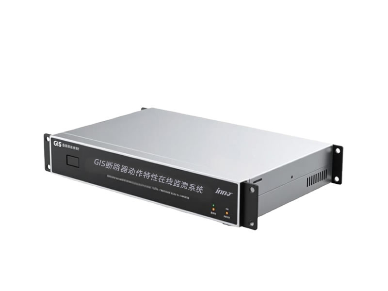
Mainframe Parameters
| Full current measurement range | 100μA~50mA | Full current measurement error | ± (nominal reading x 2% + 5μA) |
| Resistive Current Measurement Range | 10μA~10mA | Resistive current measurement error | ± (nominal reading x 5% + 5μA) |
| Measuring range of resistance-capacitance ratio | 0.05 to 0.5 | Harmonic current measurement error | ± (nominal reading x 2% + 0.01) |
| Busbar voltage measurement range | 35kV~1000kV | Busbar voltage measurement error | ±0.5% |
| System frequency measurement range | 45Hz~60Hz | System frequency measurement error | ±0.01Hz |
| working environment | Ambient temperature: -40℃~+70℃; Ambient humidity: 0~95% (no condensation) | ||
| Operating power | AC220V, ±10%; optional solar + battery power supply | ||
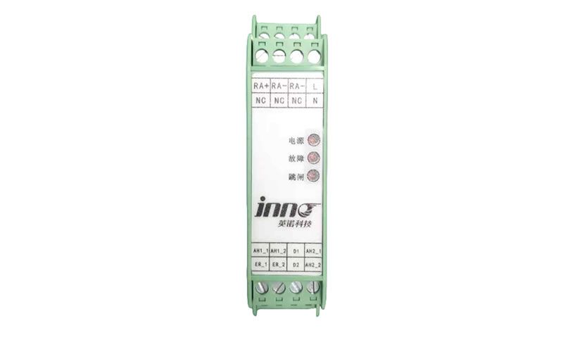
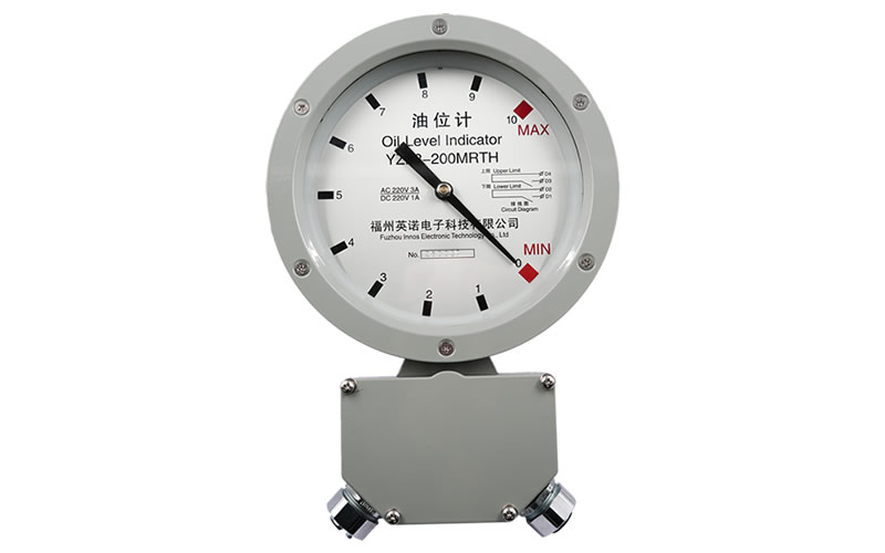
Lightning arrester digital meter
| Power supply method | external power supply | Leakage current self-powered | solar powered |
|---|---|---|---|
| communication method | Wired RS485 | cordless | / |

Active wired lightning arrester monitoring