



Product Overview
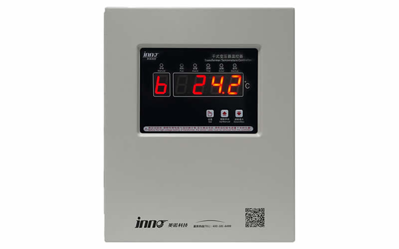
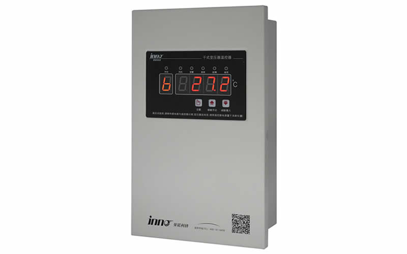
The YN-XP502F-3T Smart Monitoring Device for Dry-Type Transformers is a smart temperature control product custom-developed by Fuzhou Inno Electronics Technology Co., Ltd. specifically for temperature measurement and control applications in dry-type transformers. The device features an embedded installation design and a highly interference-resistant housing. Even under complex operating conditions involving high voltage and strong electromagnetic interference, it continues to reliably output accurate temperature data. With robust EMC and EMI performance, it is suitable for applications with stringent stability requirements, such as substations and distribution rooms.
Product Features: A 2.8-inch color LCD touchscreen with intuitive, visually rich operation; a built-in clock chip that supports time-stamped historical data logging, making it easy for operations and maintenance personnel to track the device’s operating status. The core processor uses an ARM-architecture CPU, offering powerful data processing capabilities and stable system operation. The circuit board design adheres to a modular layout that separates high- and low-voltage circuits, effectively preventing spatial crosstalk between circuits and further ensuring the device’s long-term reliable operation at the hardware level.
Core Advantages
| characterization | instructions |
|---|---|
| Multi-Channel Precision Temperature Measurement | Simultaneous data acquisition from 3 PT100 sensors for real-time monitoring of three-phase winding temperatures, with a measurement accuracy of ±1%FS |
| Colorful Touchscreen Interaction | 2.8-inch color LCD touchscreen; the main interface automatically updates the temperature every 1,000 ms; operation is simple and intuitive |
| Smart Alarm Integration | Supports automatic detection of over-temperature alarms and over-temperature trip conditions; triggers audible and visual alerts in case of abnormal conditions; and allows one-touch silencing. |
| Historical data traceability | Built-in clock chip that automatically records historical temperatures with timestamps and the highest historical temperature |
| Remote Communication Access | Comes standard with the MODBUS-RTU communication protocol, allowing connection to a host computer or backend system for centralized monitoring |
| Stable and Reliable Architecture | ARM architecture CPU + modular circuit design with separate high- and low-voltage circuits, offering strong interference resistance and stable operation |
Technical Parameter
| sports event | parameters |
|---|---|
| Number of Temperature Measurement Channels | 3-channel PT100 temperature measurement, 3-channel winding temperature measurement |
| Operating power | AC/DC 24–240 V |
| Temperature range | -30.0℃~ 240.0℃ |
| Measurement accuracy | ±1%FS (thermostat class 0.5, sensor class B) |
| resolution (of a photo) | 0.1°C |
| Control Contact Capacity | 16A / 250 V AC |
| Total Power Consumption | ≤10 W |
| working environment | Ambient temperature: -25°C to +55°C; Ambient humidity: ≤95%RH (at 25°C) |
| Installation | flush mounting |
| Overall dimensions | 96 × 96 × 84 mm (length × width × height) |
| Hole Size | 90 × 90 mm (length × width) |
| communication protocols | Standard MODBUS-RTU (addresses 1–247, baud rates 1,200–38,400, default 9,600) |
Implementation and Certification Standards
This product is manufactured in strict accordance with JB/T 7631-2016 "Electronic Temperature Controllers for Transformers" Manufactured in accordance with industry standards and certified by ISO 9001:2015 International Quality Management System Certification,ISO 14001:2015 Environmental Management System Certification,ISO 45001:2018 Occupational Health and Safety Management System Certification; simultaneously obtained IEC 61000-4:2005 International Standards and GB/T 17626-2008 "Electromagnetic Compatibility—Testing and Measurement Techniques"Through standard laboratory testing, both product quality and electromagnetic compatibility are fully guaranteed.
Smart LCD Display Interface
LCD Initialization Startup Screen
Front View of InnoTech's LCD Instrument Panel
Once the device has completed initialization, it will automatically enter the "Main Screen." Provided the sensors are properly connected, it will automatically read and display temperature data. The screen refreshes every 1,000 ms, providing a real-time view of the operating temperatures of each transformer winding, allowing operations and maintenance personnel to monitor the device’s status at any time without requiring any additional action.
① Temperature Display Area
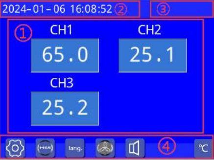
The main interface displays real-time data from all three temperature measurement channels—CH1, CH2, and CH3—simultaneously, using different colors to distinguish between various operating states for easy visualization:
| Display Information | Display normally | Thermostat Malfunction | Sensor Wire Break | Over Temperature Alarm | Over-temperature tripping |
|---|---|---|---|---|---|
| Content | 45.5 | -ER- | -OP- | 130.0 | 152.0 |
When a malfunction occurs (such as the temperature exceeding the thermostat's upper or lower limits), the screen will display -ER-; When an open-circuit fault occurs in the sensor, the screen will display -OP-; When a temperature over-limit alarm is triggered, the value is highlighted in orange; when a temperature over-limit trip occurs, the value is highlighted in red, making the alert even more conspicuous.
When any of the above conditions occur, the buzzer will automatically sound an alarm; once the alarm is triggered, the mute button icon will flash continuously to indicate the alarm. Operations personnel can simply press this button to silence the buzzer—a simple and convenient process.
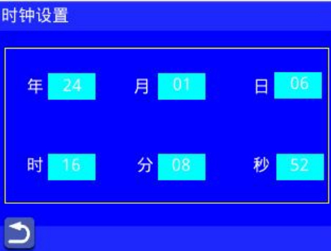
② Clock Display Area
The current system time is displayed in real time at the top of the main screen. Tap this area to access the clock settings screen, where you can adjust the year, month, day, hour, minute, and second independently. The device has a built-in clock battery, so even if the thermostat unexpectedly loses power, the clock will continue to run normally, ensuring that the timestamps in historical data records remain accurate and reliable.
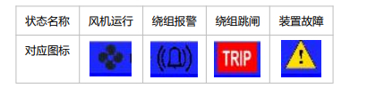
③ Function Status Indicator Area
Four status indicator icons are located in the upper-right corner of the interface, providing real-time feedback on the device’s current operating status, allowing operations and maintenance personnel to quickly grasp the overall operating status without having to enter submenus:
| Status Name | Fan Operation | Winding Alarm | Winding Trip | Equipment Failure |
|---|---|---|---|---|
| instructions | Warning Light Illuminates During Fan Startup and Operation | Lights up to indicate a winding overtemperature alarm | Light up as a warning when a winding over-temperature trip occurs | A warning light illuminates when the device malfunctions |

④ Button Area
The bottom of the main interface features five function buttons covering common operations such as parameter settings, history queries, language selection, manual fan control, and alarm silencing. The touchscreen is highly responsive, making daily operation and maintenance a breeze:
| Button | Functional Description |
|---|---|
| Settings button | Click to open the password prompt window. After entering the correct password (default: 13), you will be taken to the parameter settings menu. |
| Historical Data Key | Click to open the historical data window and view historical temperature records and the highest temperature on record. |
| Language Switch Button | Click to open the language selection screen, which supports switching between multiple languages, including Chinese and English. |
| Manual Fan Button | Click to manually start the fan. Once started, the icon’s background turns green to make it easier to identify its status. |
| Alarm Mute Button | Click to silence the current buzzer alarm—it’s simple and straightforward. |
For more product information, please contact Innotongda.
Interfaces and Wiring
The device’s terminal block layout is clear and well-organized into distinct sections: the top section contains four relay output interfaces for the fan, alarm, trip, and fault; the middle section houses the RS485 communication interface (GND / B- / A+) and the AC/DC 24–240 V power supply interface; the bottom section features three PT100 sensor terminals, along with a reserved PE ground terminal, to facilitate on-site wiring and reduce the risk of incorrect connections.
application scenario
Widely used for temperature monitoring and fan interlock control of dry-type transformers in substations, distribution rooms at industrial and mining enterprises, and container-type substations, this system helps users monitor transformer winding operating temperatures in real time, provides timely warnings of overheating risks, ensures the safe and stable operation of transformers, and reduces the risk of accidents such as power outages and damage caused by overheating.