Transformer oil chromatography online monitoring system
IN-201A Online monitoring system for transformer oil chromatography
System Introduction
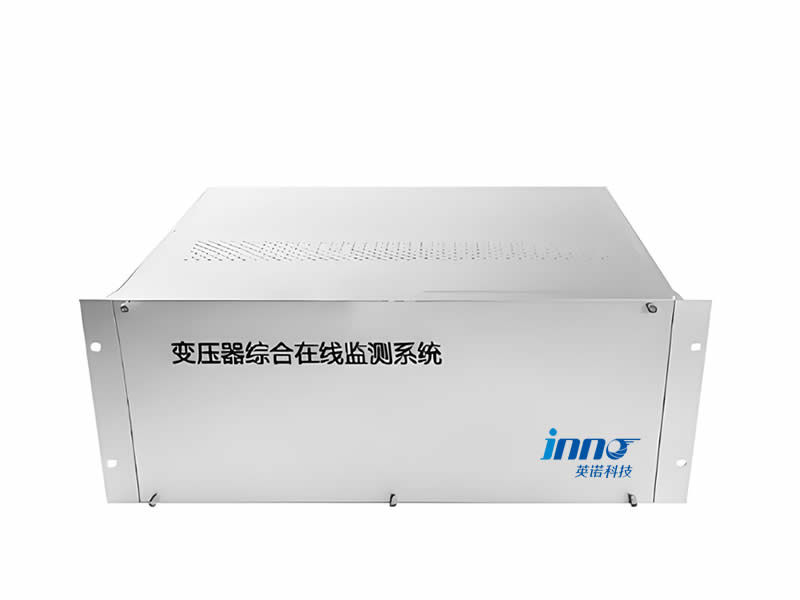
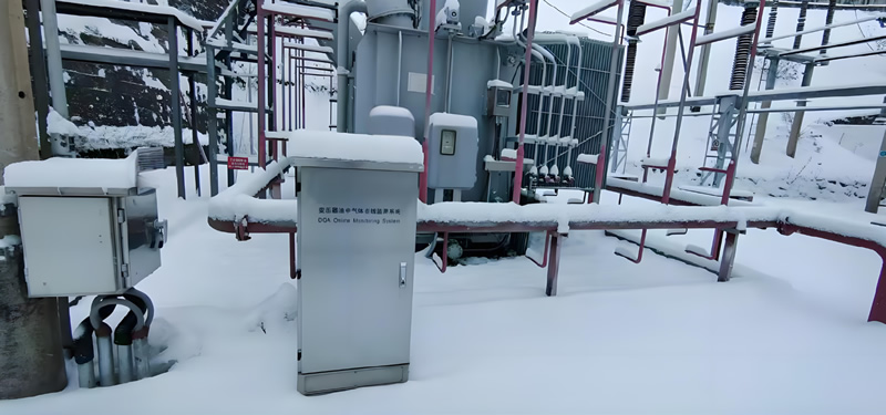
IN-201ATransformer oil gas online monitoring systemDesigned on the basis of gas chromatography principles, it integrates modules for oil/gas separation, gas detection, data processing, on-site control, communication, display (optional), power management, temperature regulation, component separation, etc., and is equipped with back-end monitoring and diagnostic analysis software (optional). The system focuses on monitoring seven key gases dissolved in transformer oil: hydrogen (H₂), methane (CH₄), ethane (C₂H₆), ethylene (C₂H₄), acetylene (C₂H₂), carbon monoxide (CO) and carbon dioxide (CO₂), and the changes in the concentration of these gases These changes in gas concentration reflect the internal condition of the transformer and potential faults. In addition, the system can also be equipped with optional indicators for monitoring core and clamp ground currents, trace moisture (H₂O), oxygen (O₂) and nitrogen (N₂).
IN-201AThe diagnostic and analysis module applies advanced machine learning and big data analytics to provide real-time monitoring and diagnostic analysis of a wide range of critical gases. Through the built-in expert system, it can intelligently identify potential failure modes, provide accurate trend analysis and early warning, and generate IEEE-compliant COMTRADE format spectrogram files that support IEC61850 (DL/T860) protocol transmission to ensure data accuracy and compatibility. At the same time, the system can also output intuitive visualization report, which is easy for users to quickly understand and take corresponding maintenance measures.
Technical Parameter
| Degassing method | headspace degassing | analysis cycle | Minimum 1 hour, programmable |
| Separation method | Blowback self-cleaning dual chromatographic columns | Detection method | Dual Channel Linear Sensors |
| Carrier gas method | High-purity gas cylinders or homemade carrier gas | data acquisition | Automatic Peak Capture, Segmented Gain |
| Input method | Automatic, quantitative | communication method | RS485, Ethernet, GPRS |
| temperature control | Dual circuit thermostat | communication protocols | Modbus, DL/T860 |
| Alarm Methods | Sound, light, in situ, remote transmission | Operating power | AC220V±10% |
Note: Other technical specifications can be customized, for details, consult our hotline 400-181-6499
Monitoring indicators
| serial number | Monitoring Objects | minimum resolution | Detection range | Detection accuracy |
|---|---|---|---|---|
| 1 | Hydrogen (H₂) | 1 μL/L | 2 ~ 2000 μL/L | ±2 μL/L or ±30% |
| 2 | Carbon monoxide (CO) | 1 μL/L | 25 ~ 5000 μL/L | ±25 μL/L or ±30% |
| 3 | Carbon dioxide (CO₂) | 1 μL/L | 25 ~ 15000 μL/L | ±25 μL/L or ±30% |
| 4 | Methane (CH₄) | 0.1 μL/L | 0.5 ~ 1000 μL/L | ±0.5 μL/L or ±30% |
| 5 | Ethane (C₂H₆) | 0.1 μL/L | 0.5 ~ 1000 μL/L | ±0.5 μL/L or ±30% |
| 6 | Ethylene (C₂H₄) | 0.1 μL/L | 0.5 ~ 1000 μL/L | ±0.5 μL/L or ±30% |
| 7 | Acetylene (C₂H₂) | 0.1 μL/L | 0.5 ~ 1000 μL/L | ±0.5 μL/L or ±30% |
Note: 1) Oxygen (O₂), nitrogen (N₂), micro-water, core clamps and other indicators can be added to monitor;
(2) Detection accuracy takes the greater of the two limits.
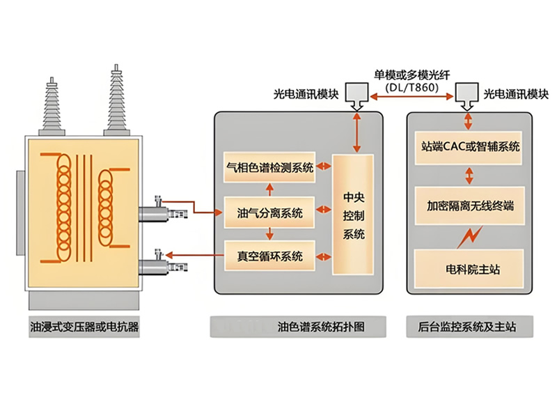
System Architecture Overview
- Applicable objects: oil-immersed transformers or reactors.
- System Objective: Online monitoring of dissolved gases and other indicators in oil, and uploading the data to the background monitoring system to realize remote alarm and operation and maintenance management.
Field side (oil chromatography system)
- Central control system: the core control and data management unit of the system.
- Gas chromatography detection system: qualitative and quantitative analysis of gases in oil.
- Oil-gas separation system: separates dissolved gases from transformer oil for chromatographic detection.
- Vacuum Circulation System: Provides stable sampling and degassing conditions to ensure test repeatability and accuracy.
- Connection to transformer/reactor: Online sampling and circulation via sampling and oil return connections.
Communication and transmission
- Optical communication module: Converts and transmits on-site inspection data via optical fiber.
- Transmission medium: single-mode or multi-mode fiber, in line with DL/T860 and other power industry communication specifications.
- Topology: Field device to station-end CAC or smart box system, and then to the backend monitoring master station.
Web site and back office
- Station-side CAC/Smartbox system: receives field data for edge-side caching, preliminary diagnosis and alarm linkage.
- Encryption isolation gateway terminal: realizes secure isolation and encrypted transmission with the superior network/dispatch network.
- The main station/backstage monitoring system of the electric power institute: centrally displaying, storing and analyzing all measurement point data, supporting trend analysis, threshold alarm, report output and remote operation and maintenance.
Key Features
- Full process coverage: from oil and gas separation, chromatographic detection to data communication and master station integration, forming an end-to-end monitoring link.
- Highly Reliable Transmission: Adopting fiber optic and industry standard protocols, anti-interference, low latency, adapting to long-distance sites.
- Expandability and compatibility: Support docking with existing station control system and dispatching system, and reserve a variety of communication interfaces and protocol adaptability.
[Product features can be customized Contact Inotera for details].


